Magnetic Contactor 1 Pole Relay Wiring

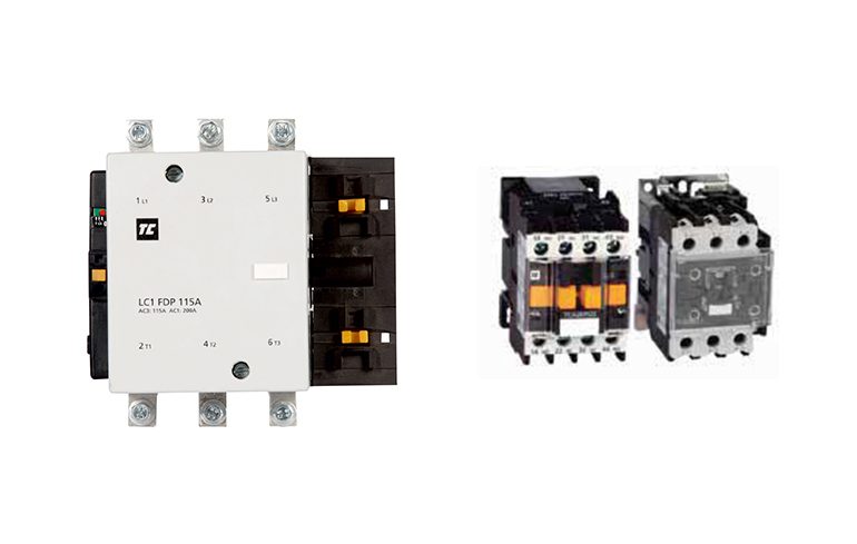
1 Vs 3 Phase Contactors Contactors Overloads Product Guides

Cooling System Air Con 20a 240v Contactor 2 Pole Ac Contactor For

Industrial Relays Finder
Single pole contactor relay wiring diagram 240v single pole means that it can only control a single circuit and single throw means that there are only two positions the switch can be in one on and one off state mechanical relays do not the esd5 series is an accurate solid state delayed interval timer it offers a 1a steady 10a inrush output and is available with adjustable or fixed time delays.
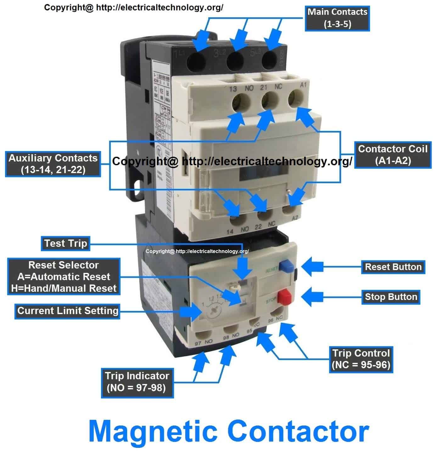
Magnetic contactor 1 pole relay wiring. Type s ac magnetic contactors36 40 class 8502 36 40 iec contactors. In 3 power system we use some devices between induction motor and supply which are a cb circuit breaker mc magnetic cont actor or motor stater ol overload relay and nc no push button switches for onoff and reset. Assortment of single pole contactor wiring diagram. A wiring diagram is a streamlined standard pictorial representation of an electric circuit.
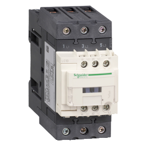
Variety of 2 pole contactor wiring diagram. Air conditioner contactor wiring diagram inspirationa wiring diagram. Contactor wiring with complete explanation. The junction relay for opening and closing the low voltage and minute current is not needed so this unit is suitable for opening and closing electronic input circuits in programmable logic controllers etc.
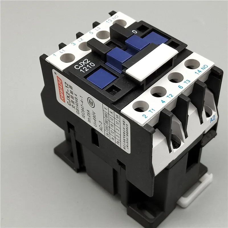
How to troubleshoot replace a contactor 1 pole vs 2 pole duration. Many large pieces of equipment are powered directly from high voltage lines. How to wire a contactor. Of magnetic contactorfor this purpose i draw a circuit diagram it is the electromagnet of the magnetic contactor a1 and a2 are the two contacts of this electromagnet when we apply 440 or 220.
Top 5 contactor troubleshooting problems. How to wire an air conditioner for control 5 wires the diagram below includes the typical control wiring for a conventional central air conditioning systemfurthermore it includes a thermostat a condenser and an air handler with a heat source. Test the start relay overload. It shows the parts of the circuit as simplified shapes and also the power and signal connections in between the gadgets.
Ac service tech llc. Contactor breakers limit switch no static control. A wiring diagram is a simplified traditional photographic depiction of an electrical circuit. It reveals the components of the circuit as streamlined forms and the power and signal links in between the tools.
240 volts ac and 480 volts ac are commonly used for these large pieces of.
Safety Precautions Of Safety Relays Cautions For Safety Relays
3 Phase Motor Magnetic Contactor Relay 12a 3p 3 Pole 1no Ac 24v

Industrial Motor Control Relays Contactors And Motor Starters

Run Stop Relay Circuit
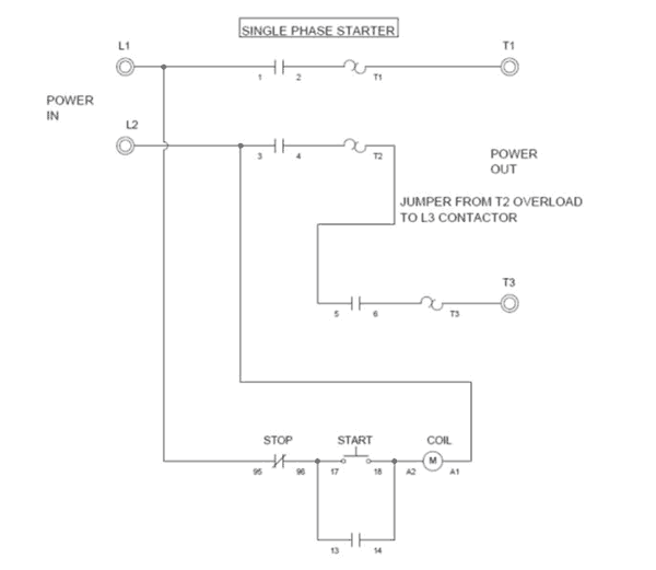
Wiring A Single Phase Motor Through A 3 Phase Contactor How And Why

Dol Starter Direct Online Starter Diagram Working Principle

Mini Contactors And Thermal Overload Relays Sk Series
Contactor Vs Relay What Is The Difference Between Relay And
Main Difference Between Contactor And Starter Electrical Technology
