Mallory Unilite Ignition Box Wiring Diagram
Unilite distributor vacuum chamber and the carburetor.
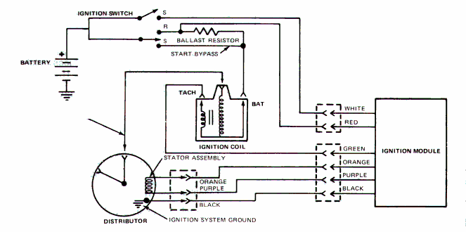
Mallory unilite ignition box wiring diagram. It shows the components of the circuit as streamlined forms as well as the power and also signal links between the tools. The unilite has 3 wires brown green and red the brown goes to ground the green connects to the msd white the red connects to the small red of the msd and both of these get power from the key switch and no resistor is needed between the key and these two reds. When a mallory unilite distributor fails to produce a spark to the plugs the vehicle will not run. Collection of mallory ignition wiring diagram.
Installing a mallory distributor two guys garage. Mallory hyfire cd box install on 95 f150. Figure 2 unilite wiring diagram using oem primary resistance wire coil ignition module female connector engine ground all other wires originally connected to the coil terminal 12vignition. The purpose of an ignition ballast resistor between the ignition switch 12v and the ignition coil positive terminal is to restrict current flow through the ignition coil.
Figure 1 unilite wiring diagram using ballast resistor ignition module female connector engine ground all other wires originally connected to. Mallory supplied much of the original equipment ignition components for ford through 1948. Even today mallory continues to build performance ignition products for ford motor company vehicles. Mallory ignition e spark and unilite breakerless distributor conversion kit installation.
The mallory unilite distributor uses an infrared light lens and a sensor between which a wheel with tangs called shutters passes. By the late 1960s the detroit plant had become too small and boots mallory began moving his fathers company to carson city nevada in 1969. The infrared light makes a completed circuit when the sensor picks it up. In this video rick from prestolite performance mallory ignition shows us how to test a mallory unilite electronic ignition module.
