Nordyne Circuit Board Wiring Diagram
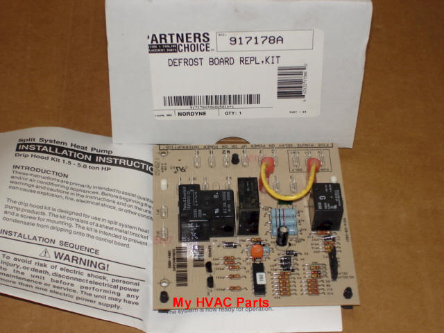
Nordyne 917178 Defrost Control Board

E2eh015ha Nordyne Electric Furnace Parts Hvacpartstore
Products Nordyne Replacement Defrost Control Board
Circuit board 2 wire relay.

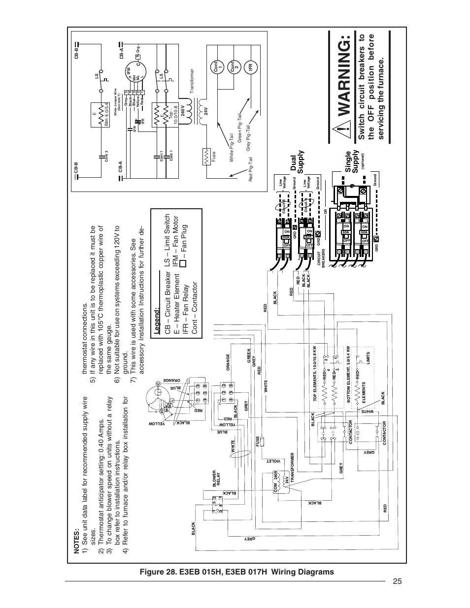
Nordyne circuit board wiring diagram. Nordyne wiring diagram electric furnace new intertherm electric. The new control board wiring assembly out of the way and carefully drill 316 diameter holes as shown in the template. Furnace air conditioner user manuals operating guides specifications. Do not use this item for any installation or repair of potable water applications.
Thermostat wiring to a furnace and ac unit. View download of more than 1019 nordyne pdf user manuals service manuals operating guides. How to know if your heat pump defrost board is working properly so that it wont freeze up. Couper le courant avant de faire letretien.
Dual capacitor h c f cch if equipped c. A wiring diagram is a simplified standard pictorial depiction of an electrical circuit. Supervision is needed by a licensed hvac tech before doing this as experience and apprenticeship garners. It reveals the parts of the circuit as streamlined shapes as well as the power and also signal connections in between the gadgets.
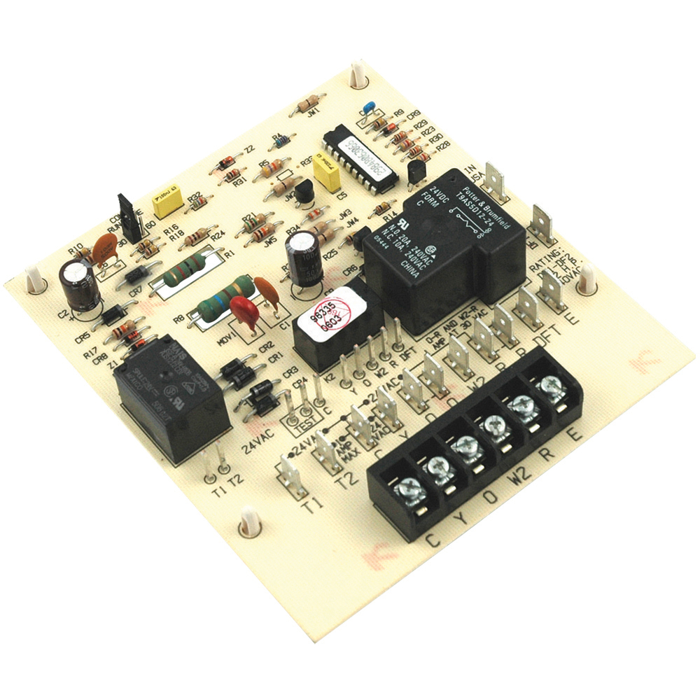
Ne convient pas aux installations de plus de 150 volt a la terre. Intertherm electric furnace wiring diagram for nordyne heat pump. This product does not comply with the safe drinking water act which requires that products meet low lead standards in order to be used in systems providing water for human consumption drinking or cooking. Position the control with the fuse toward the top and snap the feet into the mounting holes.
Coleman furnace wiring diagram heat sequencer timings nordyne. New 5 wire thermostat wire also required. Connect to 24 vac40vaclass 2 circuit. See furnaceair handler instructions for control circuit and optional relaytransformer kits.
Color code how it works diagram. Furnace circuit board has no power transformer fried due to power surge duration. Employez uniquement des conducteurs en cuivre. Replaces 624 567 624 5670 624567 6245670 624567 a.
A wiring diagram is a simplified traditional photographic depiction of an electric circuit. For a replacement order control box number 902987 along with thermostat 903992 as a replacement. It reveals the elements of the circuit as streamlined forms as well as the power as well as signal connections in between the devices. Apply the new wiring diagram for g5 furnaces.
Collection of nordyne thermostat wiring diagram. Collection of nordyne air handler wiring diagram.

Nordyne Heat Pump Wiring Diagram 917178a Wiring Diagram

Ko 7254 Wiring Diagram Goodman Aept Aepf Air Handler To Heat Pump

903106 Nordyne Miller Control Board Assembly Technical Hot Cold

Wrg 6242 Wiring Diagram For Electric Furnace

Installation Sequence For Nordyne Control Manualzz

Light Board Wiring Diagram Diagram Base Website Wiring Diagram

Intertherm Miller Nordyne Control Board 624631 624591 Ebay
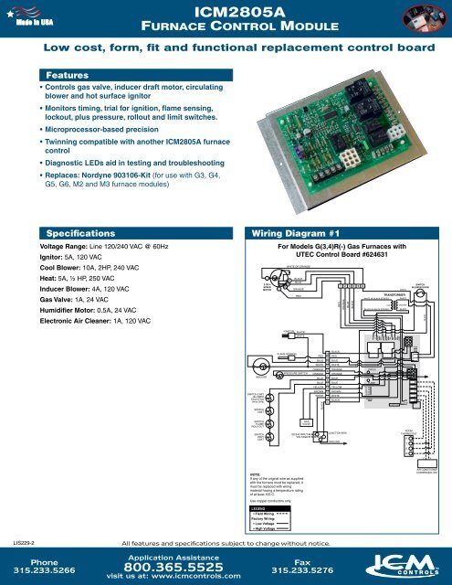
Icm2805a Furnace Control Module Icm Controls
38bcdb Nordyne Heat Pump Wiring Diagram 917178a Wiring Library
