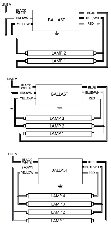
One Two Light Ballast Wiring Diagram
It reveals the components of the circuit as streamlined forms and the power and also signal links in between the gadgets.

One two light ballast wiring diagram. A wiring diagram is a simplified standard photographic depiction of an electrical circuit. Series ballasts can only be wired in series according to the diagram on the ballast. The black connects to a red power wire in the ceiling the white to the whtie neutral and the single red blue and yellow wires all connected to matching wires on the fixture to the left. How to replace ballast when wires do not match what you had.
Using two 2 lamp series ballasts. Parallel ballasts can only be wired in parallel according to the diagram on the ballast. A black a white one red one blue and one yellow. They dont have yellow wires which.
It reveals the components of the circuit as streamlined shapes and also the power and also signal connections between the devices. 4 lamp rapid start two ballasts lampholder wiring diagram. Facturer is listed for ac ballasts that have unique wiring arrangements. Vocational training and employment support service vtess our services 1.
1 using the navigation window use the navigation window and select the emergency ballast for which the diagram is needed then scroll through the list of applications to find the. No yellow wires on new ballast. A wiring diagram is a streamlined standard pictorial representation of an electric circuit. Refrigeration and aircondition rac 4.
New electronic ballast use red wires for common rather than yellow. The ballast has a hot and neutral wire at one end to receive power and two blue wires a red one. Assortment of fluorescent ballast wiring diagram. There are many types of ballasts but the simplest one is usually found in two tube light fixtures.
One 2 lamp ballast usually connects to the two middle lamps the other 2 lamp ballast usually connects to the outer two lamps. If one of the inner lamps fail the other middle lamp will not light up. Diagrams for specific situations can be located within this pdf file by using the following methods. Variety of 2 lamp t12 ballast wiring diagram.

