Op Wiring Diagram
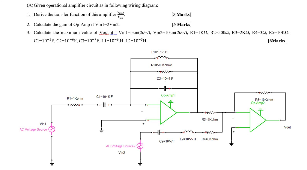
This is a differentiator circuit.

Op wiring diagram. How to properly install wiring for a 24v minn kota trolling motor with a. By connecting realistic electrical components with the wiring a pictorial diagram makes it easy and quick for viewers to identify the electrical components of a system immediately without professional knowledge required. The true differentiator is extremely susceptible to high frequency noise due to the increasing ac gain at the rate of 6 db per octave. All type for op amp circuits.
In these page we also have variety of images available. We have 14 images about op amp including images pictures photos wallpapers and more. As rich said the57 hawk diagram will work just fine. If you are looking for op amp youve come to the right place.
Radio relay schematic circuit schematic diagram schematic diagrams starter relay studebaker wiring wiring connection wiring diagram wiring diagrams wiring harnes wiring schematic wiring system wiring work. We just need to place the op amp lm741 on right place and if the op amp is in good condition then led will flash or blinks and if op amp is faulty then either led will remain on or off continuously. 16 led stoptailturn lights red white for trucktrailerjeepboatlorryvan review partsam duration. Ecm circuit wiring diagram duration.
Circuit diagram and working. If in this pic pup 1 was the neck and pup 2 is the middle couldnt i just solder the bridge pup ground along w the mid pup ground to the same lug. Circuit is very simple and we have kept is simple with few components which can be easily built on breadboard or on pcb. How to apply op amp in many project design.
Circuit diagram pin diagram sajid. Yes its labeled incorrectly. Such as png jpg animated gifs pic art logo black and white transparent etc. Pictorial circuit diagram pictorial diagrams are much easier to understand than schematic circuit diagrams.
Some are aea which is what you were looking at. Sent from my sm n915p using tapatalk 2016 ruby red ecoboost manual performance package 201a navigation enhanced security and reverse sensors. This circuit can be used to do differential operation. There are two differentiator the are true differentiator and practical differentiator.
I just want a free wiring diagram of anyone has it.