Parallel Circuit Diagram For Wiring
Labeled Parallel Circuit Diagram
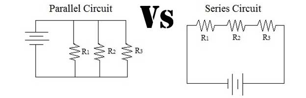
Parallel Circuit Series Circuit Diagram

Direct Current Dc Electrical Circuits By Ron Kurtus Physics
Electrical engineers mainly use this kind of circuit diagram with unified circuit symbols.

Parallel circuit diagram for wiring. Its likely though youve already read the wikipedia page about series and parallel circuits here maybe a few other google search results on the subject and are still unclear or wanting more specific information as it pertains to leds. Wiring lights in parallel connection diagram electrical blog as you know that i also written about the lights in series and in this post i am witting about the wiring lights parallel connection. Circuito integrado by luis ingles. It shows how to correctly wire a thyristor to dc.
Also if we control each lamp by single way spstsingle pole single through switch in parallel lighting circuit we will be able to switch on off each bulb from from separate switch or if we switch off a bulb the rest lighting points wont affected as is it happens only in series lighting connection where all the connected load would be disconnected. Components of an electrical circuit or electronic circuit can be connected in series parallel or series parallel. Andersen contrasts series and parallel electrical circuits. Parallel and series by emma mitchell.
Components connected in series are connected along a single conductive path so the same current flows through all of the components but voltage is dropped lost across each of the resistances. The following is a schematic circuit diagram of a semiconductor. Further as long as you can follow a path from the red wire of a light back to the positive side of the power supply through red wires and the same through black to the negative side you have wired in parallel. In a parallel circuit you will never have a black wire connected to a red wire contrasted with example of series circuit shown above.
The two simplest of these are called series and parallel and occur frequently. Hopefully those looking for practical information on electrical circuits and wiring led components found this guide first. And if you did not read the series connection of lights bulbs post or did not watch the video tutorial then watch also that video because this too important to understand the series circuit. In fact romex will be the most common cable youll use in wiring a house.
How many outlets can be on a 20 amp circuit. Look at the parallel circuits below you may find that the battery is represented as two short lines the lights are a circle with a cross inside and the wiring is displayed as a line. Tutorial for the sequence of combining resistors. Intro music atribution title.
Here the wiring is configured so that each device is in constant contact with the main circuit pathway. Im ask so many times how many outlets and or lights can i put on a 15 amp. Thyristor wiring by julian r. A simulation is used to visualize electron flow through both circuit types.
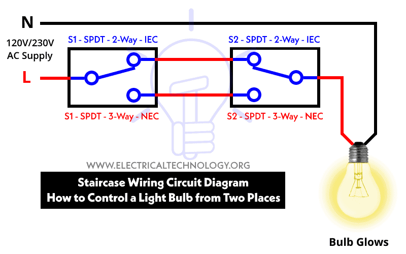
Staircase Wiring Circuit Diagram How To Control A Lamp From 2

Series Parallel Circuits

Types Of Circuits Howstuffworks

Series And Parallel Circuits Lessons Tes Teach

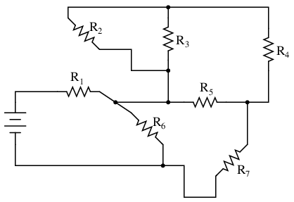
Chapter 7 Br Section C Br Re Drawing Complex Schematics
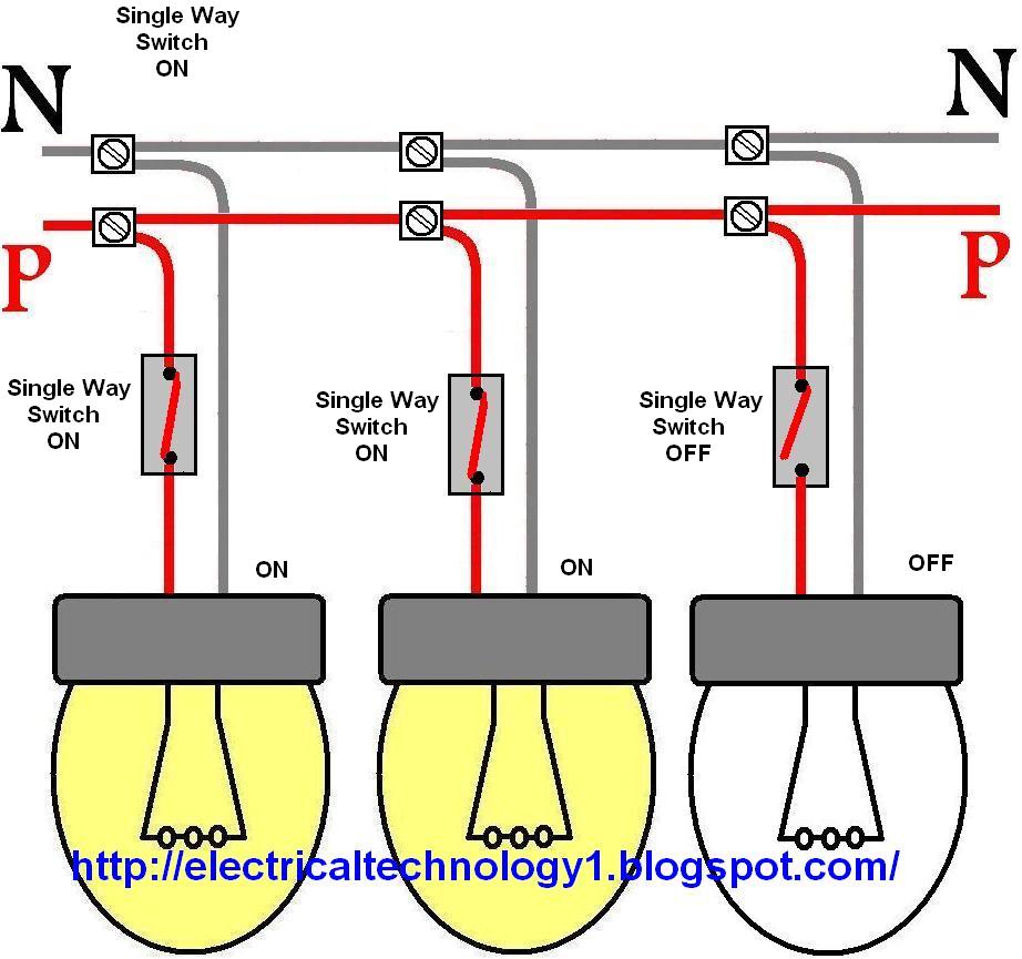
How To Control Each Lamp By Separately Switch In Parallel Lighting
Lessons In Electric Circuits Volume I Dc Chapter 7
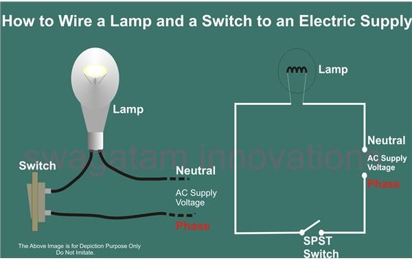
Help For Understanding Simple Home Electrical Wiring Diagrams
Wiring Leds Correctly Series Parallel Circuits Explained
