Piping And Instrumentation Diagram Nomenclature

Automatic Derivation Of Qualitative Plant Simulation Models From

Flowsheets Sciencedirect

Piping Instrumentation Diagram P Id Process Flow Systems
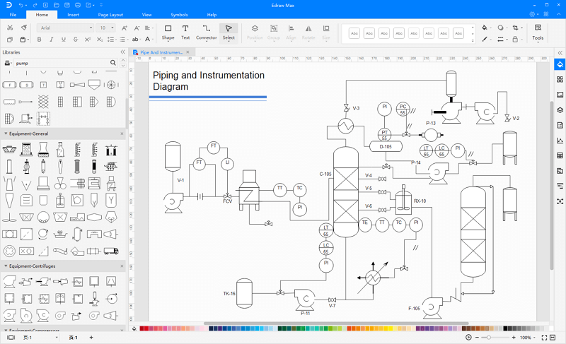
Pid piping and instrumentation diagram pid is a schematic illustration of a functional relationship between piping instrumentation and system components.
Piping and instrumentation diagram nomenclature. Pids provide more detail than a process flow diagram with the exception of the parameters ie. Process equipment valves. Superordinate to the pid is the process flow diagram pfd which indicates the more general flow of plant processes and the relationship between major equipment of a plant facility. Piping and instrumentation diagrams belong to a family.
Piping and instrumentation diagrams. Part 3 covered the nitty gritty aspects of instrumentation and control symbology. This section covers four main types of nomenclature. Along with that we dissected tag abbreviations and how loop numbers uniquely identify devices.
Piping line number identification custom search pids play very important roles in plant maintenance and modification in that they demonstrate the physical sequence of equipment and system as well as how they all connect. Isa instrumentation codes in process control systems the isa standards and symbols are important for the pids and documents describing the process control system. A piping and instrumentation diagram pid is a detailed diagram in the process industry which shows the piping and process equipment together with the instrumentation and control devices. Piping and instrumentation diagrams.
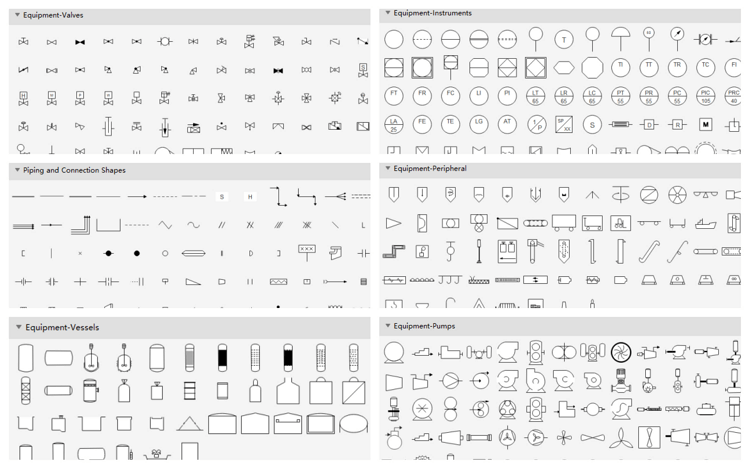
A piping and instrumentation diagram serves as an important reference that is useful at any stage of the process lifecycle. The symbology for the identification of the measurement and control instrumentation on the flow and process diagrams and on the pid piping instrument diagram commonly called pi piping instrumentation is generally compliant with the standard isa instrumentation society of automation identified as s5 that is composed of identification codes and graphic symbols. Piping and instrumentation diagrams or pids are used to create important documentation for process industry facilitiesthe shapes in this legend are representative of the functional relationship between piping instrumentation and system equipment units.
Standard P Id Symbols Legend

Process Diagrams
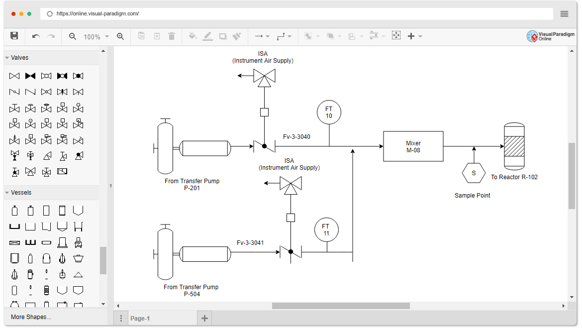
Piping And Instrumentation Diagram P Id Software
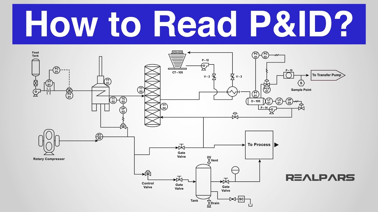
How To Read A P Id Piping Instrumentation Diagram Youtube
Https Projectcontrolsonline Com Images White Paper Processdiagrams Pdf
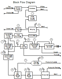
Process Flow Diagrams Pfds And Process And Instrument Drawings
Https Projectcontrolsonline Com Images White Paper Processdiagrams Pdf

P Id And Common Abbreviation Instrumentation And Control Engineering
Easy Process And Instrumentation Drawing Software
