Piping Diagram Heat Pump

Commercialization Of Air Conditioning Heat Pump Water Heater Final Technical Report Volume 2 Appendix A Through E Page 143 Of 147 Unt Digital Library

Diagram Of Heat Pipe Pv T Heat Pump System Download Scientific Diagram

Air Source Heat Pump Air Source Heat Pump Underfloor Heating Schematic
Piping connections liquid inch mm f 14 64 mmm gas inch mm f 38 95 mm drain inch mm f 1116 175 mm heat insulation both liquid and gas pipes max.

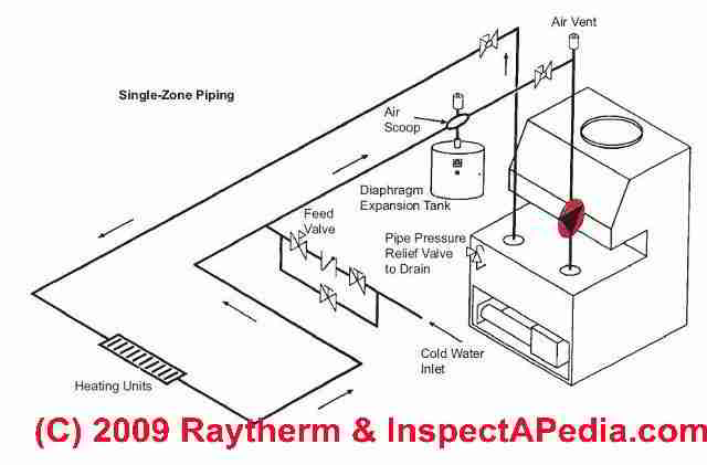
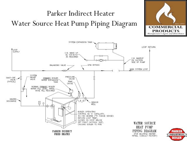
Piping diagram heat pump. Pool heat pump piping and part diagrams schematics for pool heater installations pool heater sizing charts and plumbing guides with troubleshooting tips. Always follow manufacturers instructions for both the thermostat and the hvac system. Interunit height difference feet m 26 8 m chargeless feet m amount of additional charge of refrigerant ozft. 4 shows a suggested piping arrangement in which each heat pump is piped in parallel to a common set of headers.
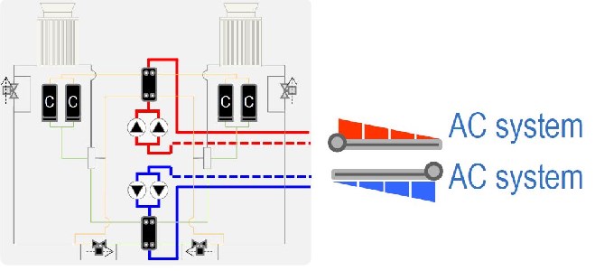
Good practice guide to heat pump installation index of figures and tables 4 10 introduction 7 20 heat pump systems 8 21 types of heat pump systems 8 22 components of a heat pump 10 23 how a heat pump works 12 24 fixed speed and inverter compressors 12 30 heat pump performance 13 31 heat pump efficiency 13 32 energy rating label 14. Two or more water to water heat pumps can be used in a staged configuration much like multiple boilers. You can also view the 2 modes showing the refrigerant states with buttons 4 and 5. A piping and instrumentation diagram pid is a detailed diagram in the process industry which shows the piping and process equipment together with the instrumentation and control devices.
Additional articles on this site concerning thermostats and wiring can help you solve your problem or correctly wire a new thermostat. Click back and forth between buttons 2 and 3 and note how the discharge from the compressor is diverted to different coils in each mode. Figure 4 please see print edition for fig. A water source heat pump extracts heat from the water when in the heating mode and rejects heat to the water when in the cooling mode.
Heat pump thermostat wiring chart diagram hvac the following graphics are meant as a guide only. The water supply may be a. The circulator associated with each heat pump runs only when that heat pump is on. A heat pump is a device that transfers heat energy from a source of heat to what is called a thermal reservoirheat pumps move thermal energy in the opposite direction of spontaneous heat transfer by absorbing heat from a cold space and releasing it to a warmer onea heat pump uses external power to accomplish the work of transferring energy from the heat source to the heat sink.
Raypak pool spa residential and commercial hydronic products. Water source heat pump unit operation a water source heat pump is a mechanical reverse cycle device that is used to transfer heat from one medium to another.
Heating System Circulator Pump Location Mounting

Residential Air To Water Heat Pumps Plumbing Hvac

Hydronic Heat Pumps Chillers
Multi Function 4 Pipe Heat Pumps Explained Upgrade Approach
Parker Boilers Indirect Pool Heaters

Heat Pumps
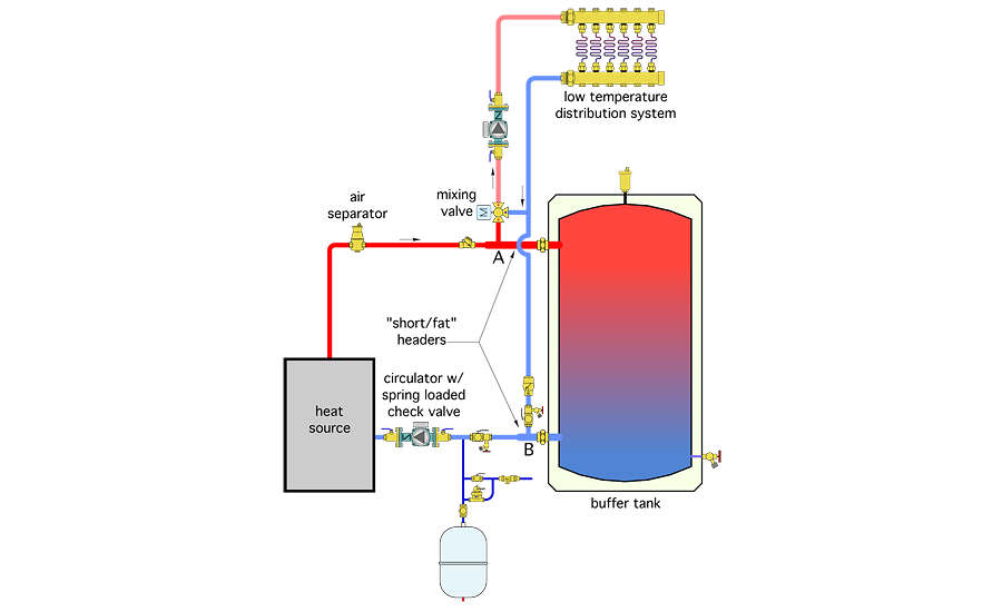
Different Ways To Pipe A Thermal Storage Tank 2016 03 22 Pm Engineer
Https Www Osti Gov Servlets Purl 1330528
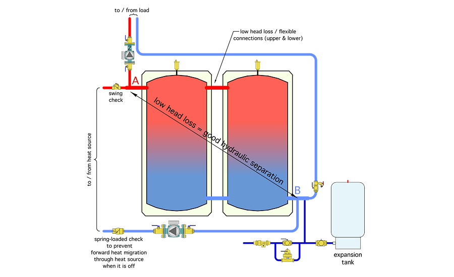
Different Ways To Pipe A Thermal Storage Tank 2016 03 22 Pm Engineer
