Piping Instrumentation Diagram Picture

A Piping And Instrumentation Diagram P Id Is A Schematic

Preliminary Piping And Instrumentation Diagrams P Ids Unitel
P Id In Autocad Creating Piping And Instrumentation Diagram
As i mentioned in part 2 the meanings of the various symbols used on pids aka symbology are defined on separate drawings called lead sheets or legend sheets.
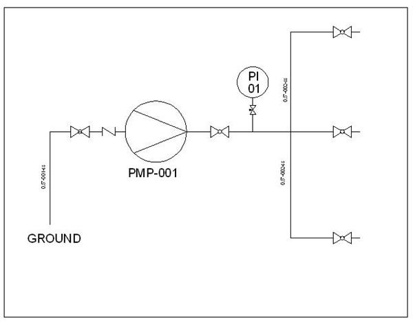
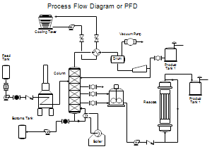
Piping instrumentation diagram picture. Size rating throughput and utility usage. A piping and instrumentation diagram displays the piping components for example equipment valves reducers and so on of an actual physical process flow and is often used in the engineering projects such as setting up steam boilers heat exchangers electric boilers and more. A piping and instrumentation diagram or pid shows the piping and related components of a physical process flow. Piping and valves symbols.
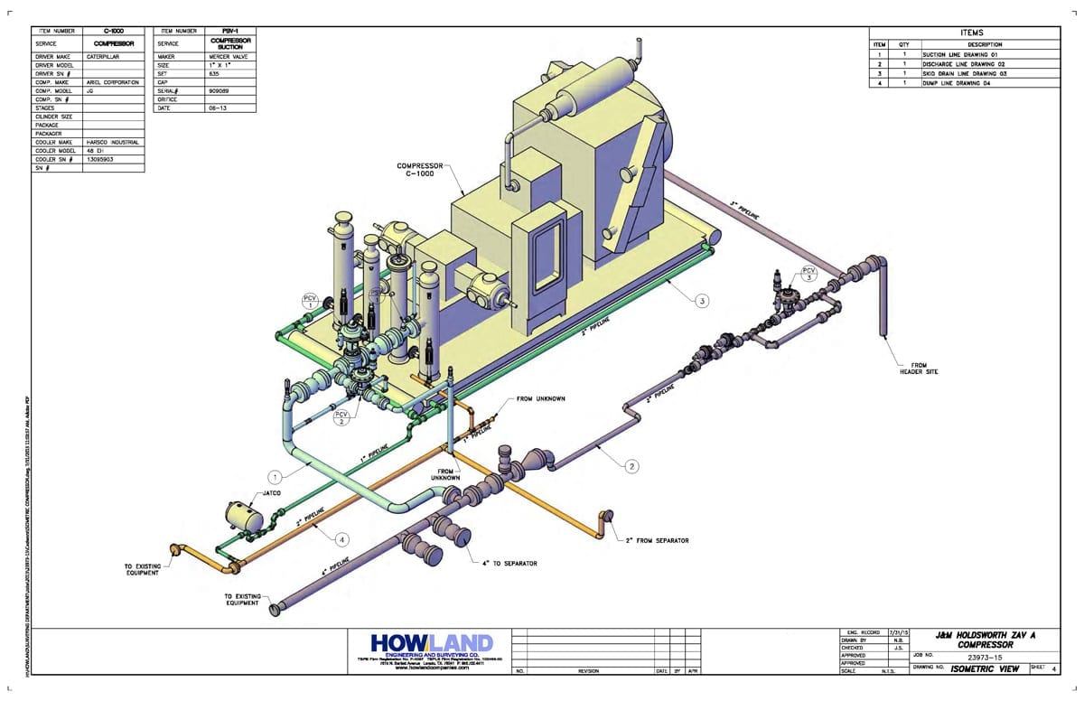
A pid provides information to begin planning for construction of plant. Thermal power plant piping and instrumentation modern factory. Lifelike symbols help create presentation quality piping and instrumentation diagrams. See more ideas about piping and instrumentation diagram mechanical engineering design diagram.
Add to likebox. There are different sets of symbols are used to depict mechanical equipment piping piping components valves drivers and instrumentation and controls. Affordable and search from millions of royalty free images. A pfd is a picture of the separate steps of a process in sequential order.
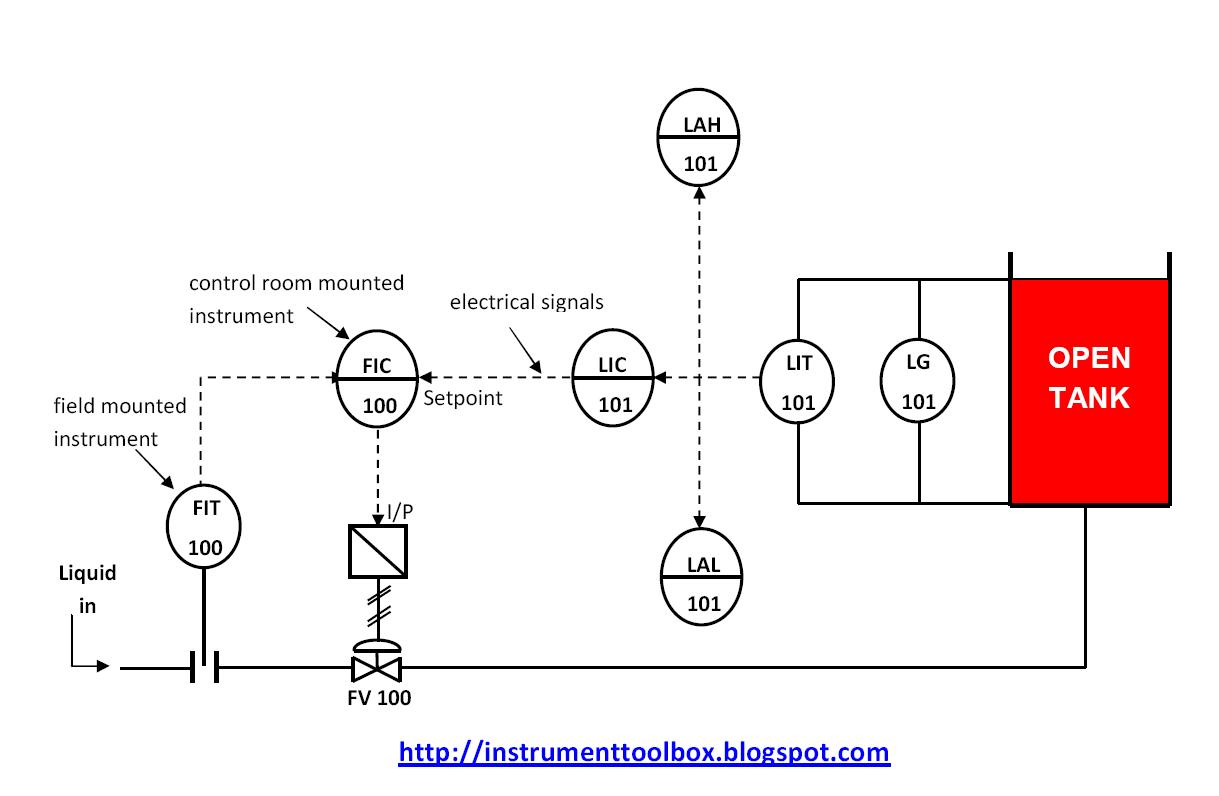
Also a fluid system diagram may also depict instrument signals and electrical wires as well as piping. Plumbing and piping plans solution from the building plans area of conceptdraw solution park provides the following 4 vector stencils libraries. Piping and instrumentation diagram software. Apr 10 2020 explore josephragusins board instrument on pinterest.
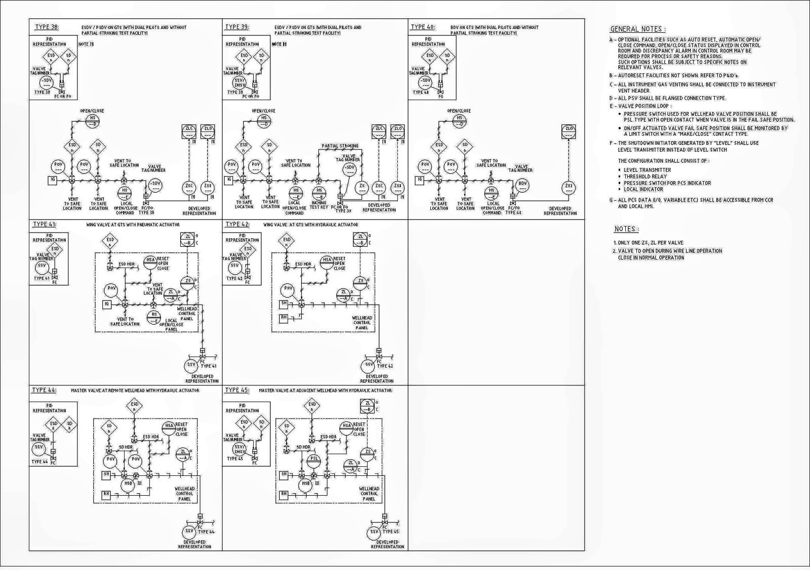
Piping and instrumentation diagram concept many uses in the. Nov 30 2019 explore iammichaelferrells board piping and instrumentation diagram on pinterest. More than 2000 vector piping and instrumentation diagram symbols are provided including ductwork symbols valves pumps motors blowers chillers tanks logistics production process symbols hvac symbols and much more. Figure 7 shows commonly used symbols for indicating the medium carried by the piping and for differentiating between piping instrumentation signals and electrical wires.
A pid digram contains following information regarding the equipment. Get a thorough explanation of symbology as it relates to piping and instrumentation controls symbology tag identification io devices valve symbol primary flow element horizontal line types dashes and more. See more ideas about process control piping and instrumentation diagram electronic engineering. Use the design elements libraries pipes 1 and pipes 2 for drawing plumbing and piping building plans schematic diagrams blueprints or technical drawings of waste.

Piping Instrumentation Diagrams Guide Lucidchart

Pipe Instrument Diagram Of Reactor Process Download Scientific
Piping And Instrumentation Diagram Symbols

Piping And Instrumentation Diagram Wikipedia
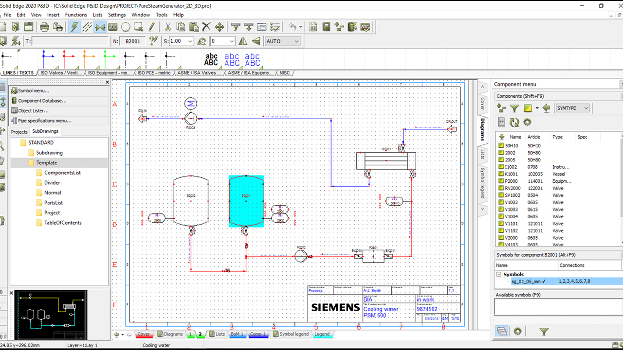
Piping And Instrumentation Diagrams Siemens
Piping And Instrumentation Diagrams Tutorials Iii Flow And Level
Process Flow Diagrams Pfds And Process And Instrument Drawings

B Dep Piping And Instrument Diagram Appendix
Piping Instrument Diagram Common Symbols Field Instrumentation
