Power Control Wiring Diagram
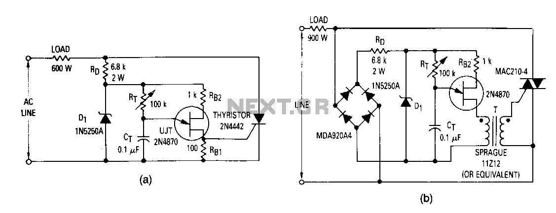
Phase Control Circuit Under Inside Circuits 9908 Next Gr

Wiring Diagram Electrical Wires Cable Schematic Access Control

Unacart Global Online Shopping Store For Electronics Home
Feb 5 2020 explore elects59s board electrical diagram on pinterest.

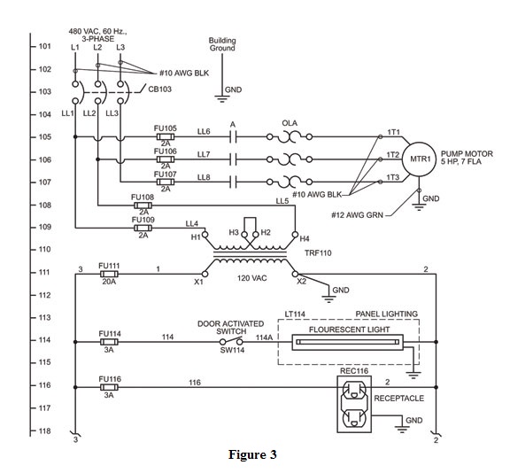
Power control wiring diagram. Up tp 93 off. It reveals the components of the circuit as simplified forms and also the power and signal links in between the gadgets. See more ideas about electrical diagram electrical circuit diagram electrical engineering. Figure 4 control power transformer wiring diagram.
A wiring diagram is a streamlined traditional photographic representation of an electrical circuit. In this tutorial we will show the star delta y d 3 phase induction ac motor starting method by automatic star delta starter with timer with schematic power control and wiring diagram as well as how star delta starter works and their applications with advantages and disadvantages. Short circuited brewers 45265 views. Three phase motor power control wiring diagrams 3 phase motor power control wiring diagrams three phase motor connection schematic power and control.
Jun 22 2014 three phase motor power control wiring diagrams 3 phase motor power control wiring diagrams three phase motor connection schematic power and control. Control wiring control wiring as its name implies has as its main purpose transmitting electricity used for control purposes. A wiring diagram is a simplified traditional photographic depiction of an electrical circuit. Control wiring carries low levels of current because not much current is required for control purposes such as energiz.
A very detailed wiring diagram analysis video and part of our wiring diagram and automotive electronic series here on this channel. Here well go into details on the newer computer controlled. In this way the primary of the transformer is supplied with the same voltage as the powermotor circuit of the starter. It shows the elements of the circuit as streamlined shapes and the power and signal links between the gadgets.
Variety of control transformer wiring diagram. The leads from the primary of the transformer are connected to l1 and l2 on the starter.

Charge Controller High Side Low Side Wiring Diagrams Part 2

How To Construct Wiring Diagrams Industrial Controls

Ats Auto Transfer Switch Power Control Diagram Auto Change
.png)
Access Control Cables And Wiring Diagram Kisi
A Condensed Guide To Automation Control System

Dol Starter Circuit Wiring Diagram Valid Motor Starter Control

Pk152 Tektone Power And Control Unit Wiring Diagram

Wiring Diagram Of The Control Driving And Power Circuits Of

Power Turbine Control System N2 Wiring Diagram Continued
