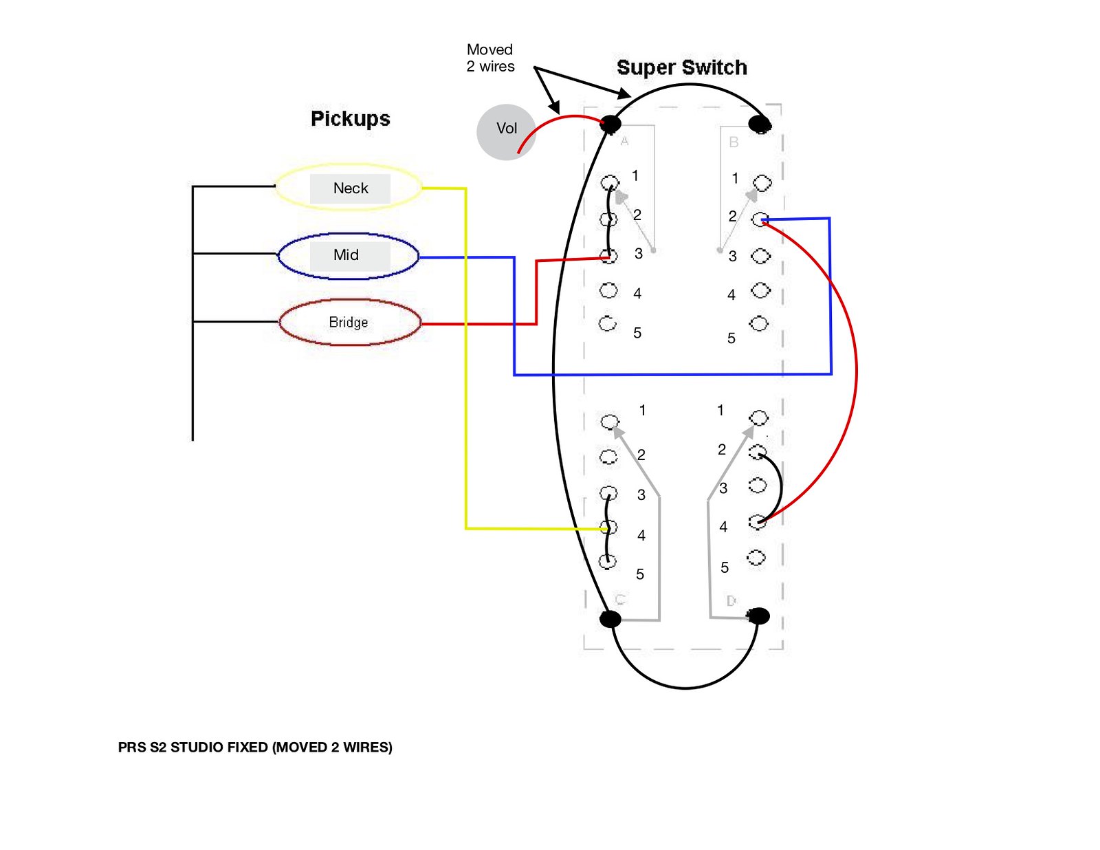
Pr S2 Wiring Diagram
Moulded case circuit breaker series launched in 1993 was available in different versions and is now obsolete.

Pr s2 wiring diagram. Here i am telling what each terminal if for. Sace isomax s series ranged from s1 to s8 with rated uninterrupted currents i u from 125 to 3200a with ultimate rated breaking capacity i cu from 10 to 200ka 380 415v. Usa 5 tan dar d d r aft n g p rae t c e s electrical and electronics diagrams usas y1415 1966 usa standard approved includes the following. Y yellow is compressor g green for fan.
R red is hot 24 volts o orange reversing valve w white is heat. Label wiring diagram kb 81 286 wb 51 211 dwg no. 3203 prprx table of contents 71410 introduction 1 10 general specifications 1 30 safety tips and precautions 2 10 operating practices warnings 2 30 qualifications for operators 2 40 operation of unit outriggers 2 70 inspection 3 10 testing 3 40 maintenance 3 50 batteries 3 70 lubrication and maintenance schedule 3 90. Lbl20116 model title material blank mv 102609.
Inlet sensor s2 flue sensor s3a flue sensor s3b integrated control bk y gas valve at24vac spark rod transformer tr2 g. Net vpn pps e serr ocal ser pps lan an s2050616 access control s2 netbox software version 4102 and later s2 network node blade m1 3200 application blades sios 7 portals 14 access levels 512 supervised inputs 56 relay outputs 56 temperature inputs 56 credential storage 150000 buffered transactions 800000. Label wiring diagram kb 400 801 dwg no. Register or login to mylutron.
Lbl20127 model title material blank mv 2410 mc 41410. Search the lutron archive of wiring diagrams. 2w 2 wire 3w 3 wire 4w 4 wire if 2w or 3w is selected the end user must ensure that the applied sensor wiring does not introduce failures exceeding the requirements for the safety application. 15 a ventilador 300 w luz 120 v 60 hz notas importantes centro de soporte tecnico de lutron 18005239466 instalacion instalaciones de unidades multiples cuando combine controles en la caja de embutir elimine todas las secciones laterales internas.
Pr or br br pr pr cn2 4 cn2 1 cn1 5 cn1 6 cn1 3 cn1 4 cn1 1 cn1 2 k1 k2 k3 relay board onoff switch. Not a network diagram. 15 1 scope 15 2 definitions. Kb 801 only blower t high limit sensor s1b operating sensor s1a inlet sensor s2 flue sensor s3a flue sensor s3b integrated control bk y gas valve.
To find a diagram for a specific product or system please use the drop down menus below. 15 a ventilador 300 w luz 120 v 60 hz s2w lfsq. Controles para luz y ventilador s2 lf. These devices were developed for ac and dc distribution and were available in fixed plug in and withdrawable version.
Page 63 9116 universal converter safety manual connec selected sensor connection type for rtd or linear resistance measurements for sensor ni or pt or intype linr. Specifications s2 network node schematic only. Product quick links.