Proces Flow Diagram Ga Plant

Process Flow Diagram Of Methanol Synthesis Loop Via Natural Gas
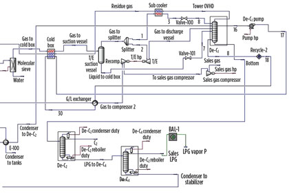
Retrofit An Lpg Plant For Improved Output And Ethane Recovery

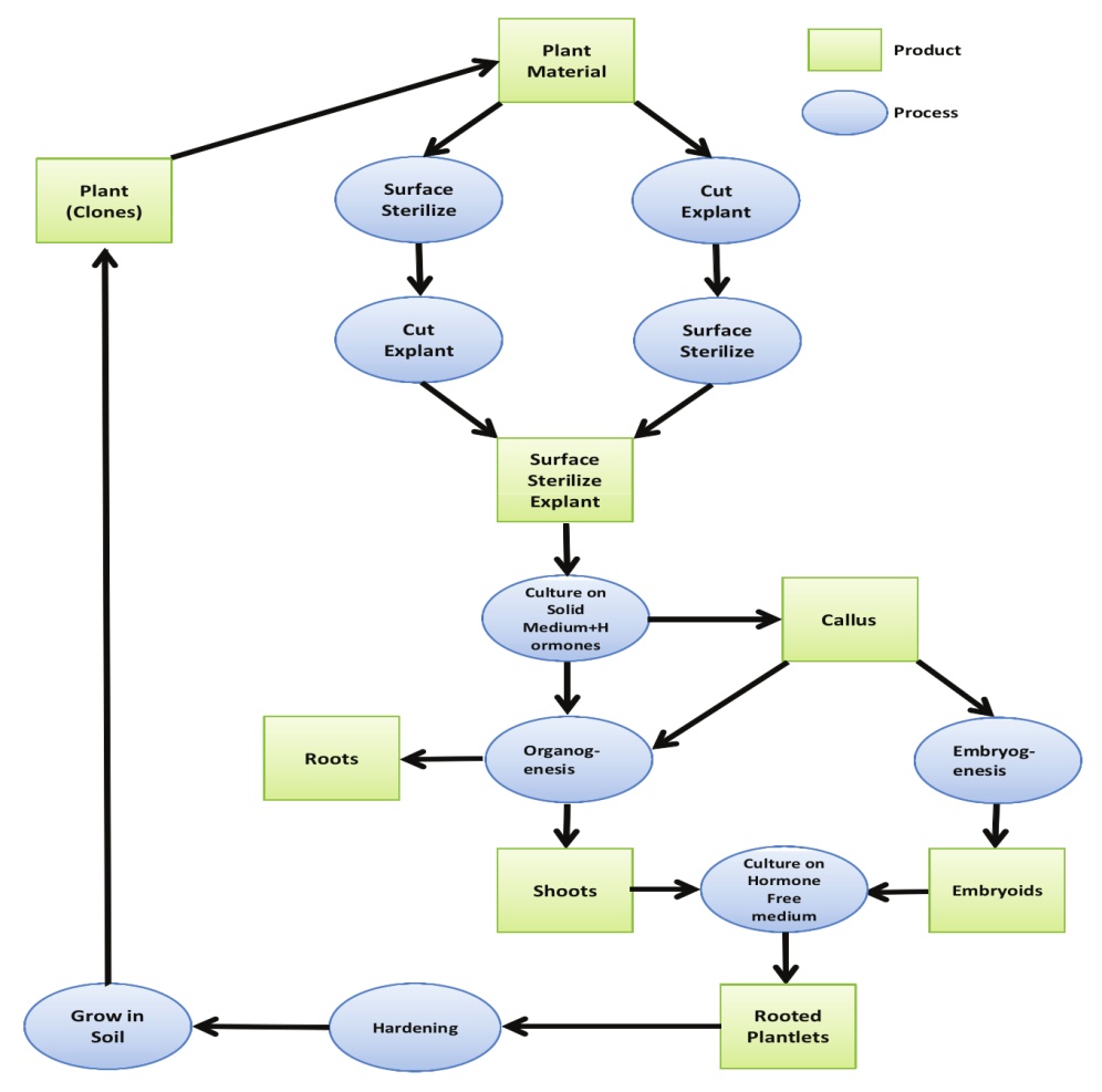
National Plant Board Plant Quarantine Nursery Inspection And
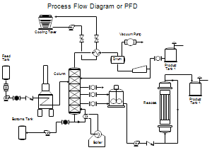
Process flow diagrams pfds are used in chemical and process engineering.
Proces flow diagram ga plant. Most processes can be displayed visually using a process flow chart. Since a process can be seen as a kind of algorithm the practice spread into the business. From plant to plant the lng process duration. The concept of the flow chart was once tied to the realm of software development where it was necessary to analyze the algorithms that were being programmed.
Alabama powers plant miller how electricity is generated 3d animated tour. Dehydration process diagram natural gas duration. The four processes are. Pfds are used for visitor information and new employee training.
Glycol dehydration is a liquid desiccant system for the removal of water from natural gas and natural gas liquids ngl. Glycols typically seen in industry include triethylene glycol teg diethylene glycol deg ethylene glycol meg and tetraethylene glycol treg. 01 feb 2011 d. This article throws light upon the four processes of waste water treatment.
As discussed in chapter 2 sections 22 and 23 safety is a key. Teg is the most commonly used glycol in industry. Mohammed alhassani 46634 views. Final check of.
The composition of the raw natural gas extracted from producing wells depends on the type depth and location of. Generally a process flow diagram shows only the major equipment and doesnt show details. Woodside energy 141185 views. Pid is sometimes referred to as a piping and instrumentation drawing.
1 preliminary treatment 2 primary treatment 3 secondary or biological treatment and 4 tertiary or advanced treatment. These diagrams show the flow of chemicals and the equipment involved in the process. A piping and instrumentation diagram pid includes more details than a pfd. Figure 72 schematic process flow diagram for tubular high pressure process for production of low density polyethylene.
Lng terminal flow duration. Plant operating manuals project standards and specifications page 6 of 19 rev. Lng plant animation mohamed emad 93. Here is a simple process flow diagram example.
Natural gas processing is a range of industrial processes designed to purify raw natural gas by removing impurities contaminants and higher molecular mass hydrocarbons to produce what is known as pipeline quality dry natural gas. Pids are mostly used by process technicians and engineering personnel. Natural gas processing begins at the well head. It is the most common and economical means of water removal from these streams.
It consists of both major and minor flows control loops and instrumentation.

Control Valve Handbook

Process Safety Management Occupational Safety And Health
Process Flow Diagrams Pfds And Process And Instrument Drawings

Plant Kingdom Classification And Characteristics Plant

Process Flow Diagram For Bolivar Sewage Treatment Facility For

Piping And Instrumentation Diagram Wikipedia
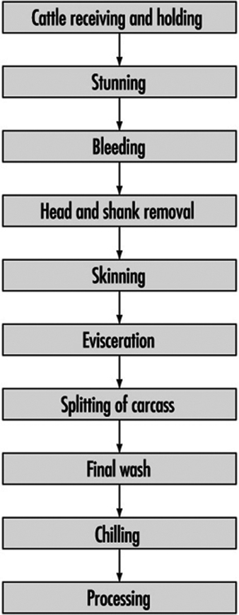
Food Processing Sectors
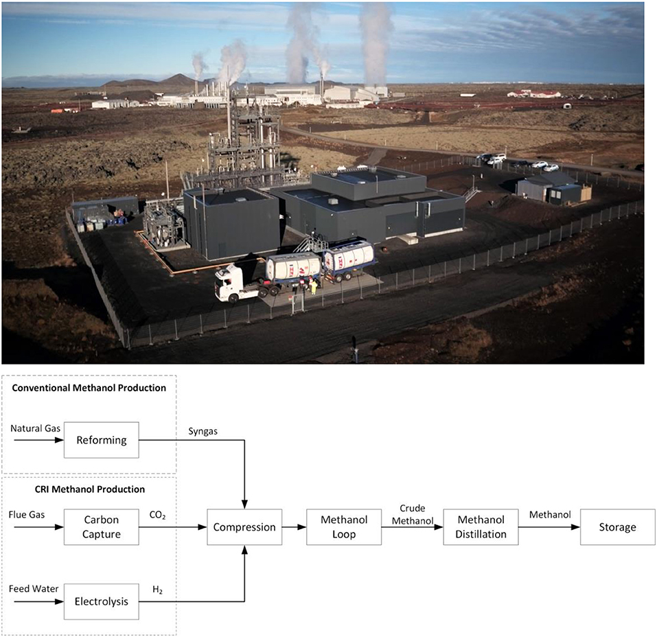
Frontiers Process Advantages Of Direct Co2 To Methanol Synthesis
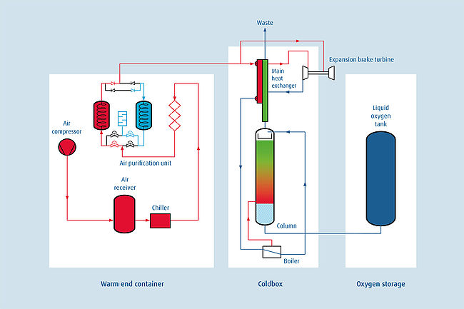
Cryogenic Oxygen Plant Wikipedia
