Pt100 3 Wire Rtd Wiring Diagram
Http Cache Automation Siemens Com Dnl Iis Ju Juxotg2nwaa 59753600 Hb Et200sp Ai 4xrtd Tc 2 3 4 Wire Hf Manual En Us En Us Pdf
2 3 And 4 Wire Rtds What Is The Difference

3 Wire Rtd Sensor Wiring A 3 Wire Rtd 3 Wire Rtd Probe
3 wire pt100 rtd sensor wiring system.

Pt100 3 wire rtd wiring diagram. A wiring diagram is a simplified standard photographic representation of an electrical circuit. What do the different color wires on my rtd mean and how do i physically connect them. 3 wire rtd wiring diagram awesome rtd sensor temperature ppt video. 2 wire rtd connections the 2 wire rtd configuration is the simplest among rtd circuit designs.
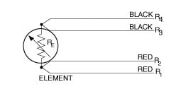
What is an rtd rtd types uses and more by jms southeast. A 2 wire configuration with a compensating loop is also an option. It reveals the parts of the circuit as simplified forms and also the power and also signal links between the devices. For example heres the approximate resistances of a 4 wire pt100 rtd at 0 0 c for a pt1000 the middle resistance would be 1002 w rather than 102 w remember that the middle resistance 102 or 1002 w will vary with temperature but the 2 w wires will not when the amp measures this sensor it will measure the resistance between one set of red and blue wires.
Pt100 temperature sensor wiring diagram below. I have a 2 wire 3 wire or 4 wire resistance temperature detector rtd that i want to connect to my data acquisition daq device. Sor resistance temperature detector rtd proflow systems. It is very important that each of the three wires used in the measuring circuit are equal in terms of both conductor size and length.
Rtd wiring configurations there are three types of wire configurations 2 wire 3 wire and 4 wire that are commonly used in rtd sensing circuits. A1b1 a2b2 and c1c2. There are 2 wiring methods for the rtd module and pt100 temperature sensors two wire and three wire connections. A wiring diagram is a streamlined standard photographic depiction of an electrical circuit.
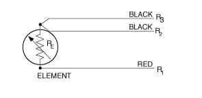
Assortment of rtd pt100 3 wire wiring diagram. It shows the components of the circuit as streamlined shapes and also the power and also signal links between the gadgets. Collection of 3 wire rtd wiring diagram. Pt100 in 3 wire connection.
The influence of the lead resistance is compensated to the greatest possible extent with a 3 wire connection. The requirement for this is that the lead resistances are the same as can be assumed with a 3 wire connection. The addition of a third wire connected to one side of the measuring element helps to compensate for the lead resistance.
Rtd Sensors 2 3 4 Wire Rtd Sensors Resistance Temperature Detectors
2 3 And 4 Wire Rtds What Is The Difference

4 Wire Rtd Wiring Diagram Diagram Base Website Wiring Diagram

Resistance Thermometer Wikipedia

Excitation Current Mismatch Effects In Three Wire Rtd Measurement

Overview Adafruit Max31865 Rtd Pt100 Or Pt1000 Amplifier
Doc Tinkerforge

China Fst600 202 Cylinder Head Temperature 2 Wires Rtd Pt100

3 Wire Rtd Diagram Fiat 22 Slaapsneller Nl
