Push Button Latching Relay Wiring Diagram
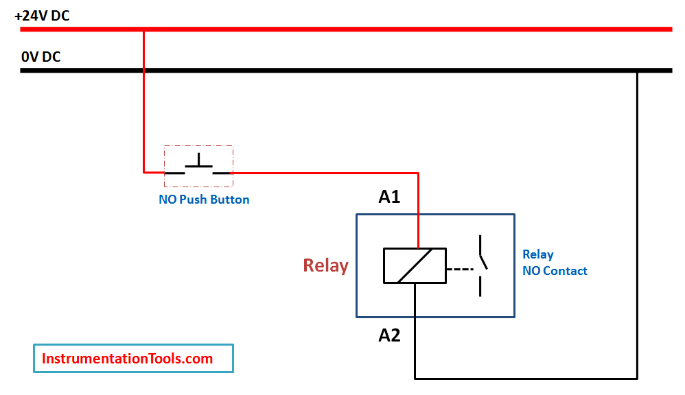
Relay Latching Circuit Using Push Button Instrumentation Tools
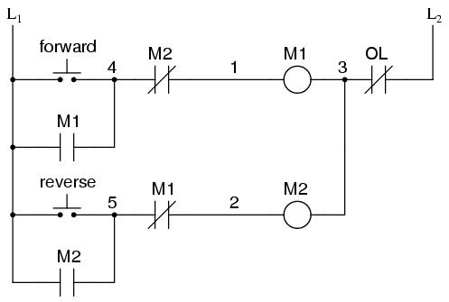
Ladder Logic
Dc Relay Diagram Diagram Base Website Relay Diagram Ballard
The relay only draws current when it is being switched.
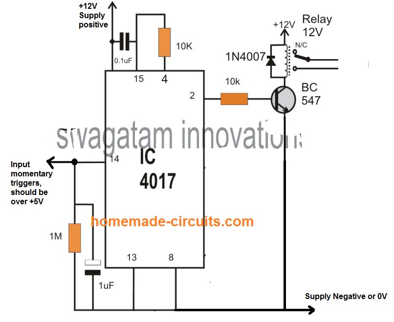
Push button latching relay wiring diagram. For example use this as a dip switch with a push button switch to change between main beam and dip and vice versa. Here relay is 24 v dc operated. To use this latching relay circuit just press the button connected to relay 1 and the load will stay on even if the button is released. Step 2 when supply comes to relay coil relay should be on.
The only problem is that it takes a little while to set up it doesnt look the nicest and it is rather large. These two step we see in following picture relay latching circuit using push button. When we press push button relay should be on it means we use normally open type push button because when we press this switch supply goes forward. Or put another way you need a slow speed bistable.
You press it in and it clicks on and when you press it again it clicks off. Push on push off circuit latch circuit. Latching relay to use a momentary button ok i know that you can make a latching relay with the diagram provided on this site. Wiring up a push button mictuning.
In this video i will show you how to make touch on touch off switch with relay. 19mm 22mm billet automotive buttons wiring diagram video rgb. I have done it and it works great for my application. For those wondering what this mean a latching button act like a toggle switch.
But it should reset itself back to when input voltage drops to zero. Then only the free wheel diodes are needed and its perhaps a safer. Momentary buttons on the other end are only active when you hold them pushed. But you also need to debounce the push button otherwise bounces will put you in a random state.
To stop just press the button connected to relay 2 and the load will turn off and stay off until you push the 1st button again. The easiest latching relay circuit to understand ever. 12v 25a with resistor. It was originally intended to allow a single pushbutton switch on the dash of a vintage car to provide a latched function.
12v latching relay this relay is a change over relay that can be remotely controlled by a momentarily on switch. I think youd find it much easier to use two push buttons one green one for on and a big red emergency stop push button for off. Diagram of simple one button push. The correct schematic diagram.

Electrical Switches Wiring Diagram Push Button Electrical Polarity
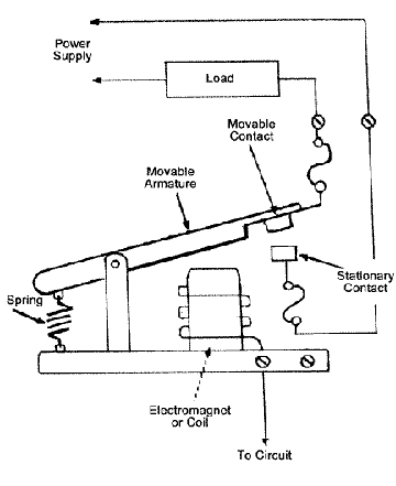
How Relays Work Relay Diagrams Relay Definitions And Relay Types

Ac Relay Power Switch Circuit

Unph38 1

Single Pulse Push Button Door Locks With Images Automotive

Edn Cmos Circuit Latches Relays

Latching Relay With Kill Switch Electrical Engineering Stack

12v Relay Latching Until No Power Electrical Engineering Stack
9 Pin Latching Relay Wiring Diagram Schematic Wiring Diagram
