Reading A Ladder Logic Diagram
No more hard wired logic but memory locations instead.

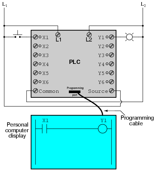
Reading a ladder logic diagram. Ladder diagrams sometimes called ladder logic are a type of electrical notation and symbology frequently used to illustrate how electromechanical switches and relays are interconnected. Circuits are connected as horizontal lines ie the rungs of the ladder between these two verticals. The ladder diagram consists of two vertical lines representing the power rails. How to read a ladder logic program.
In a plc there is full flexibility to change the sequence of operations and interlocks for different conditions. It is a graphical plc programming language which expresses logic operations with symbolic notation. Ladder diagrams are drawn vertically with inputs on the left and outputs on the right. Ladder logic also known as ladder diagram or ld is a programming language used to program a plc programmable logic controller.
For this program the relay logics ladder diagram is duplicated with ladder logic. Autocade simples for ladder logic. Lets take a look. In drawing a ladder diagram certain seven conventions are adopted.
The symbols displayed are given in an autocad drawing for learners. The two vertical lines are called rails and attach to opposite poles of a power supply usually 120 volts ac. What is ladder logic. Ladder logic is made out of rungs of logic forming what looks like a ladder hence the.
Each rung of the ladder has output. Reading and understanding ladder logic once the hardwire relay logic concepts are understood then its easy to comprehend ladder logic. There are integrated circuits and internal.