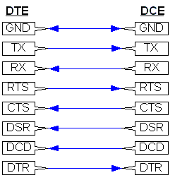
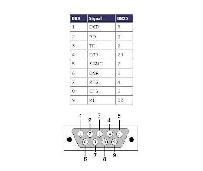
Rj45 To Db9 Wiring Diagram
This article shows how to wire an ethernet jack rj45 wiring diagram for a home network with color code cable instructions and photosand the difference between each type of cabling crossover straight through ethernet is a computer network technology standard for lan local area network.

Rj45 to db9 wiring diagram. Db9 to rj45 adapters are often used in combination with a. The complete ethernet pinout cable wiring reference with wiring step by step guide. Figure 1 is the wiring scheme for the plug side of an rj 11 connector. If you never crimped a rj45 before please refer to this video.
The standard formerly known as rs 232 or rs232 became eia 232 then tia 232. Collection of convert rj11 to rj45 wiring diagram. Lets start crimping the rj45 connector. I personally use tiaeia 568a wiring diagram to all my cables so i will continue doing so.
Pin 9 on the db9 side is not usedfor the rj45 side while facing the module the. This is a straight thru adapter cable pin 1 1 2 2 3 3 etc. Click to find view print and more. Just make sure you follow in this case tiaeia 568a wiring diagram.
It reveals the parts of the circuit as simplified shapes and the power as well as signal connections in between the devices. It was introduced commercially in 1989 and became ieee standard 8023 in 1983. The typical rj 11 connector has six terminals. Remember the rj45 wiring order.
Click to check the right one for you or print as reference. The part number for reordering the rj45 to db9 adapter cable provided with plc serial modules is cable 14pinout for the db9 side. The t 568b standard is the most commonly used. View looking into male connector male and female connector diagrams rs232 on rj45 rs 232d more properly eiatia 561.
Most of the world still. Network wiring instructions for rj11 and rj45 rj 11 telephone plug. Rj45 pinout diagram shows wiring for standard t568b t568a and crossover cable. Figure 2 is the wiring scheme for the plug side of an rj 45 connector in accordance with t 568b standards.
The wall jack may be wired in a different sequence because the wires may be crossed inside the jack. The diagram is shown with the hook clip on the underside. Use when connecting to or from a serial port with a 8 position modular jack rj45.
