Single Line Wiring Diagram Timer

How To Wire On Delay Timer

Low Temperature Defrost Timer Wiring Diagram Box Diagram Base

Types Of Automatic Pumpdown Control Systems
Up tp 93 off launching official electrical technology store.

Single line wiring diagram timer. The above is a star delta starter wiring diagram 3 phase motor for main wiring. Then connect the switched wire typically a blue wire to the black wire leading to the device. Three phase motor control and design power circuit and installation. Direct on line starter.
Consult your timers wiring diagram to ensure which wire is the hot lead from the switch. You can feel so completely satisfied when being the member of this on line wiring diagram single phase motor collection. Once again we below offer you not only in this kind of wiring diagram single phase motor. Clap switch circuit using ic 555 timer without timer.
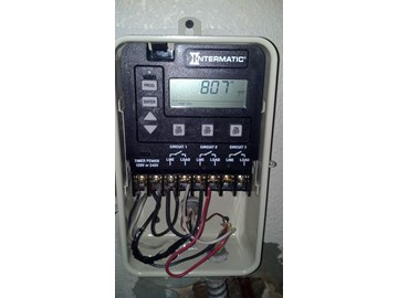
Wiring diagram book a1 15 b1 b2 16 18 b3 a2 b1 b3 15 supply voltage 16 18 l m h 2 levels b2 l1 f u 1 460 v f u 2 l2 l3 gnd h1 h3 h2 h4 f u 3 x1a f u 4 f u 5 x2a r power on optional x1 x2115 v 230 v h1 h3 h2 h4 optional connection electrostatically shielded transformer f u 6 off on m l1 l2 1 2 stop ol m start 3 start start fiber optic. Three phase and single phase. Variety of intermatic 240v timer wiring diagram. A single phase induction motor consists of a single phase winding on the stator and a cage winding on the rotor.
At the end of the delay period the. Now lets see the star delta starter control circuit diagram with timer ncno push button switches. You can also locate the various other electrical wiring diagram compilations from worldwide. Single line wiring diagram timer furthermore star delta starter motor control with circuit diagram in in addition how to construct wiring diagrams industrial controls further contactor wiring guide for 3 phase motor with circuit in addition forward amp reverse 3 phase ac motor control circuit diagram as well electrical how do i replace a single pole light switch in addition wiring diagram for.
Clap switch circuit using ic 555 timer without timer. It shows the components of the circuit as simplified shapes as well as the power as well as signal links in between the devices. Star delta starter control circuit diagram. Schematic and circuit diagram.
Also called interval interval delay when power is applied to the input voltage terminals the load is energized immediately and the time delay cycle starts.
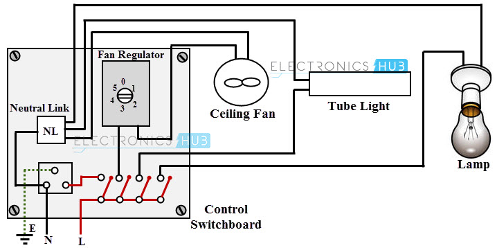
Electrical Wiring Systems And Methods Of Electrical Wiring

Precision Multiple Controls Official Website Your Source For

Star Delta Control Circuit Circuit Diagram Electrical Circuit

Electricity 101 Basic Fundamentals Industrial Controls
Https Encrypted Tbn0 Gstatic Com Images Q Tbn 3aand9gcr7jxmvl35pd Eozp 8t44sdn3hktniz Vsfgorptraoog W1f Bpbllv6k4ok6yxg Usqp Cau
How To Wire A Pe153 Digital Timer To A 2 Speed 230v Motor

Outdoor Standard Push Button Timer Outdoor Timers And Switches

Single Phase Motor Wiring With Contactor Diagram With Images
Https Encrypted Tbn0 Gstatic Com Images Q Tbn 3aand9gcstsnogbvukbyyd7ma9sytlttwy Eumivblgnayi6kkm4yffhmvrfrknd6osey3ncs Usqp Cau
