Single Timer Wiring Diagram
Single Line Wiring Diagram Timer Wiring Diagram
Wiring Diagrams Washing Machines Macspares Wholesale Spare

Wiring Diagram Single Pole Contactor With Timer Wiring Diagram
Wiring capacitors resistors.

Single timer wiring diagram. It shows the parts of the circuit as simplified shapes and also the power and signal connections in between the gadgets. A wiring diagram is a simplified standard pictorial depiction of an electrical circuit. It reveals the elements of the circuit as streamlined forms and also the power and signal links in between the gadgets. A wiring diagram is a streamlined standard pictorial representation of an electric circuit.
It can be used in one shot or delay timers to produce a time delay. Single phase dwelling services101 table 12 awg and. Assortment of single pole contactor wiring diagram. Consult your timers wiring diagram to ensure which wire is the hot lead from the switch.
We have a light switch box containing three single pole switches no ground terminal in the foyer near the front door. I would like to replace the light switch controlling the porch lights with the honeywell programmable timer switch rpls740bgiven the following conditions i could not determine any wiring combination such that all related electrical components worked. 555 timer ic is a useful precision timing device produces single pulses or as an oscillator producing a string of stabilized waveform of any particular duty cycles. The danfoss contactor and timer panels are primarily designed for snow and ice melting applications.
A single phase induction motor consists of a single phase winding on the stator and a cage winding on the rotor. Wiring diagram book a1 15 b1 b2 16 18 b3 a2 b1 b3 15 supply voltage 16 18 l m h 2 levels b2 l1 f u 1 460 v f u 2 l2 l3 gnd h1 h3 h2 h4 f u 3 x1a f u 4 f u 5 x2a r power on optional x1 x2115 v 230 v h1 h3 h2 h4 optional connection electrostatically shielded. All panels are pre wired and ul listed complete with a nema 1 enclosure wiring diagram terminal connection block timer timer panels and two or four 3 pole contactors. Clap switch circuit using ic 555 timer without timer.
Assortment of single phase submersible pump starter wiring diagram. Staircase timer wiring diagramstaircase timer connectionstaircase timer working principle duration. Full house wiring diagram using single phase line video.

3x3x3 Led Cube Circuit With Images Electronics Projects Diy
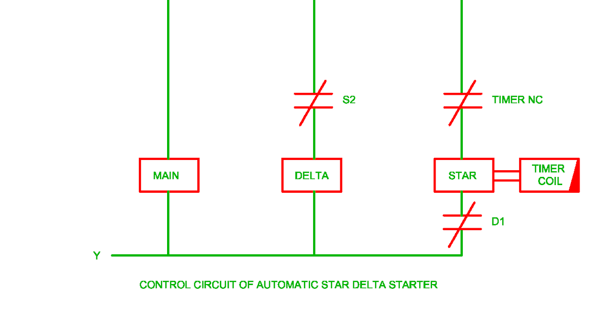
Star Delta Control Circuit Diagram With Timer Pdf لم يسبق له مثيل

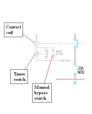
Contactor Wiring Diagram With Timer Diagrama De Circuito
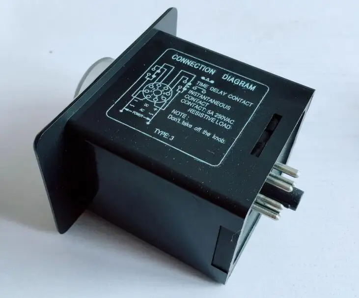
Anly Timer Wiring Diagram

How Do I Replace A Single Pole Light Switch With A Programmable
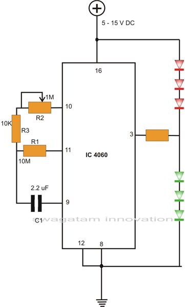
How To Make Interesting Ic 4060 Circuits Bright Hub Engineering

How Do I Replace A Single Pole Light Switch With A Programmable
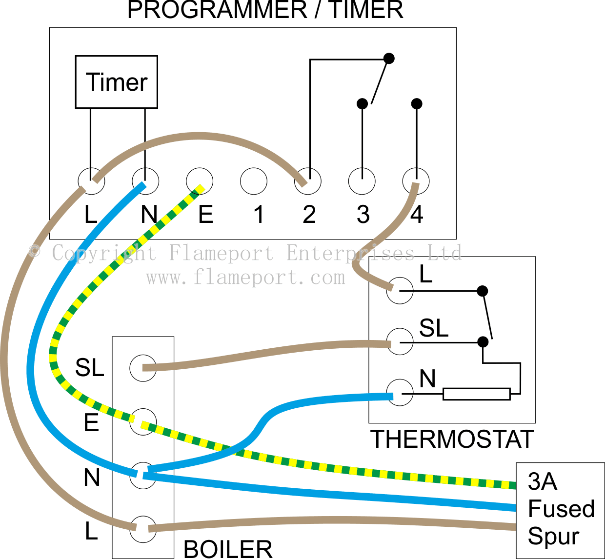
External Programmers For Combination Boilers
Kubota Timer Relay
