Solder Xlr Connector Wiring Diagram

Tx Afc1f Balanced To Unbalanced Audio Transformer Xlr Rca

Usb Audio Dac With Pcm2704

Xlr Wiring Diagram Poli Repeat9 Klictravel Nl
The most comon way to wire a 3 pin xlr to a 14 inch 65mm mono plug sometimes called a jack plug is to join the negative and shield together.

Solder xlr connector wiring diagram. The positive and shield of the xlr are joined together either at the xlr end or the rca end. Collection of xlr wiring diagram pdf. Set aside some. This can be done by either soldering the shield and negative wires of the xlr to the sleeve of the plug.
Speakon to 1 4 wiring diagram 14102018 14102018 5 comments on speakon to 1 4 wiring diagram the issue im having is that it does not have 14 inch outputs used a meter to find out which wire was positive and that is the tip of the 14 plug. Learn how to make your own cables like the pros. The easiest way is to solder a link between pins 1 and 3 shield and negative of the xlr rather than trying to solder the shield and negative wire to the sleeve contact of the rca. Here is the essentials for soldering xlr and mic cables.
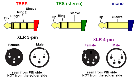
Links to products used in the description below. 3 pin xlr connectors are standard amongst line level and mic level audio applications. The rear view is the end you solder from here are the connections on each pin. Xlr to 14 mono plug.
If theres a white wire inside your cable your positive end will be red or blue if theres a blue wire with no white wire your positive end will be red. Neutrik nl2mp speakon connector 2 pole panel mount regarding neutrik speakon connector wiring diagram image size x px and to view image details please click the image. This produces an unbalanced audio cable. Any helpful comments.
You can also find other images like images wiring diagram images parts diagram images replacement parts images electrical diagram images repair manuals images engine diagram images engine scheme diagram. Customarily the shieldground copper wire is always going to be associated with 1 the positively charged red or blue wire associated with 2 and the negatively charged white blue or green or black wire associated with 3note. A wiring diagram is a simplified standard photographic depiction of an electric circuit. The above diagram shows you the pin numbering for both male and female xlr connectors from the front and the rear view.
3 pin xlr wiring standard. If you dont have time to watch a massive video on soldering technique.

Combo Xlr 1 4 Connectors

Electronic Wiring Majorcom
Headphone Attenuation Adapter Diy Audio Heaven
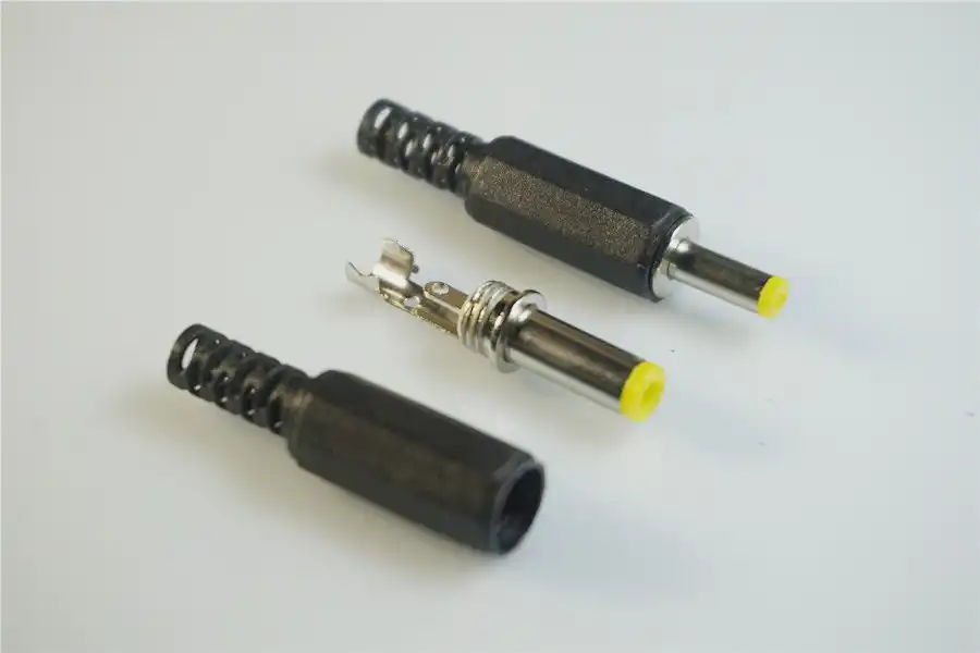
10 Pcs Diy 5 5 Mm X 2 5 Mm Dc Power Plug Female Wire Cable Solder
Microphone Cable Riddle Recording Studio Forums

Mini Jack To Xlr Wiring Gp Www Thedotproject Co

The Importance Of Star Quad Microphone Cable Benchmark Media Systems

Zy 2996 Trs Cable Furthermore Stereo Trs Dual Xlr Audio Cable

Xlr Audio Wiring Rain Www Calc4web De
