Starter Motor Diagram Picture

Alternator Or Generator With Images Automotive Mechanic
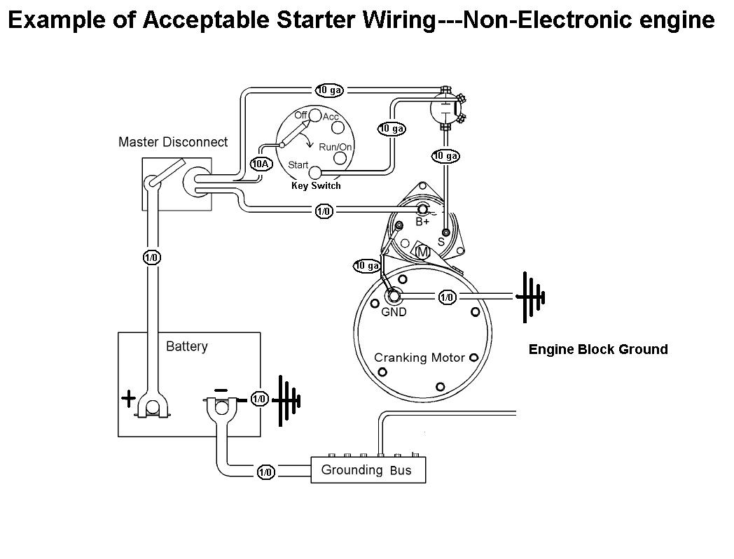
Acceptable Starter Motor Wiring With Mag Switch

Simple Starter System Scheme Of Vehicle Download Scientific Diagram
A starter also self starter cranking motor or starter motor is a device used to rotate crank an internal combustion engine so as to initiate the engines operation under its own power.
Starter motor diagram picture. Line voltage control three phase 3ph motor starter controlling a three phase motor rev 08 aug 2006 the above wiring diagram assumes your magnetic starter has a 240v coil. Other solenoids mostly on fords are remote mounted. If you have a 120v coil instead of running a line from coil overload l2 you must run coil overload neutral. Starters can be electric pneumatic or hydraulicin the case of very large engines the starter can even be another internal combustion engine.
Starter motor components engine starting system is a system that have a function to crank the engine for the first time. The result is a rotating crank and engine cycle can be triggered to work continuously. The working principle of starter motor is to rotate the engine crankshaft via flywheel using electric motor circuit. Starting system wiring diagram.
Here is a picture gallery about starter motor solenoid wiring diagram complete with the description of the image please find the image you need. In many cases today the anti theft computer or module will cut or deactivate the starter due to an. This video will show the correct location for wiring a starter motor on a c3 corvette. These solenoids are.
The security starter relay controlled car starter wiring diagram is as shown in the following picture. Here is a picture gallery about starter motor diagram wiring complete with the description of the image please find the image you need. A wiring diagram is a kind of schematic which utilizes abstract photographic symbols to show all the interconnections of parts in a system. Internal combustion engines are feedback systems which.
Before the engine starts the alternator does not generate electricity the voltage of the neutral tap n binding post is zero no current passes through the charge light relay starter relay coil and charging indicator relay contacts are connected to ground. Most vehicles use a starter mounted solenoid that functions as a high power switch to connect the starter drive pinion gear with the flywheel to start the engine. Most on starter solenoids are easy to wire as you mount the starter on the engine. Video is demonstrated on a 1969 corvette.
This video also shows some still photos embedded into the video of. Eaton motor starter wiring diagram whats wiring diagram.

Bmk1055r Ca45 Cav Starter Motor Charnleys Tractor Parts

Diesel Engines Starter Circuit Tests Diesel Engine Troubleshooting

Unph32 6
Using Car Starter Motors On Your Robot
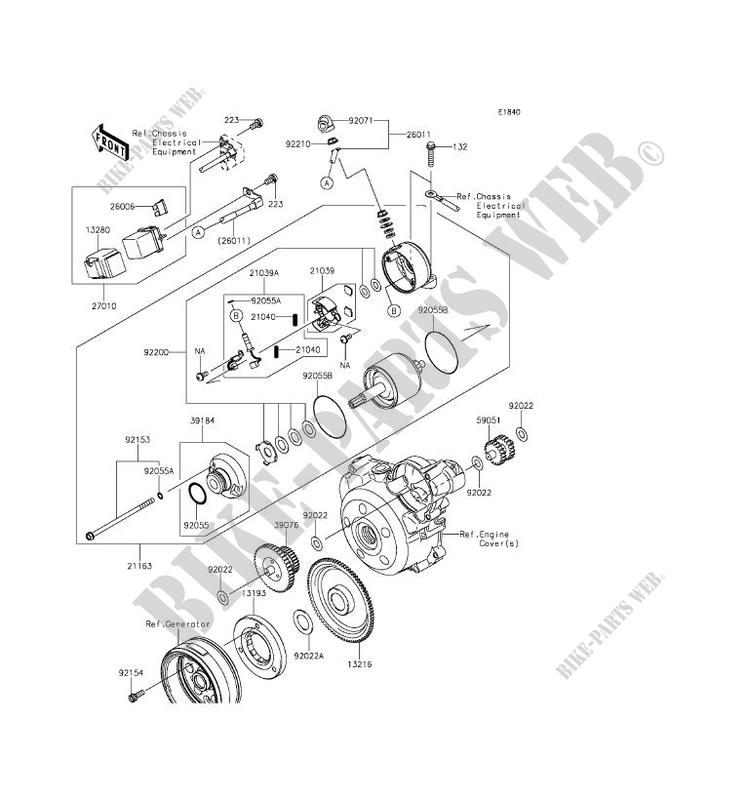
Starter Motor For Kawasaki Klx140 2017 Kawasaki Genuine Spare

Sliding Armature Starter Motor
Starter Motor Function
General Starter Motor Wires What Goes Where The Fiat Forum
Starter Motor Labeled Diagram
