Stepper System Wiring Diagram
3 Phase Digital 3 Wire Stepper Motor Driver 220v 3dm2080 For Nema

Stepper System For Computer Control Of Telescopes

Learn Before You Buy
It makes the procedure for assembling circuit easier.
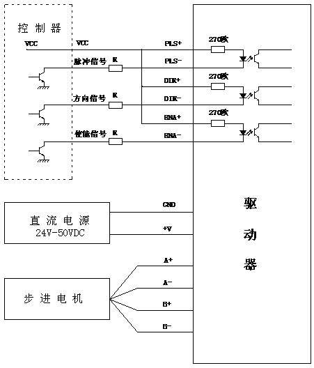
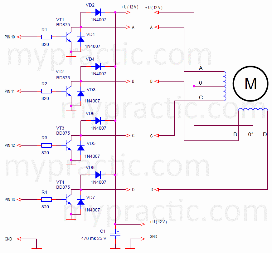
Stepper system wiring diagram. Outputs q0q9 of the counter go high in succession in response to the rising edges of the clock signal. Since coils a and b on the diagram above are not connected the resistance between leads a1 and b1 or between a1 and b2 will be infinite. Ic1 generates a square wave signal with a frequency that can be set using potentiometer p1. Route highvoltage power cables separately from lowvoltage power cables.
On the other hand the diagram is a simplified variant of this structure. The diagram provides visual representation of a electrical structure. Stepper motor wiring diagram elegant ponent series circuit diagrams. Nema 17 step motor wiring diagram you should know oyostepperover stepper motor wiring diagram.
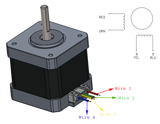
If your stepper motor has 4 wires it is a bipolar stepper motor. Segregate input power wiring and stepper motor power cables from control wiring and motor feedback cables as they leave the steper motor driver. This is a really easy method to identify a matching set of coils for a stepper motor when the vendor or manufacturer doesnt have it or wont provide it. The grey code is generated by a decimal counter in the form of a 4017.
The following diagram shows the connections to be made for an 8 wire series connected bipolar stepper motor. Follow the wiring diagram with each stepper motor. Stepper motor wiring diagram elegant ponent series circuit diagrams. Maintain this separation throughout the wire run.
For questions and quotes please contact. This frequency determines the rpm of the stepper motor. Bipolar stepper motors have two windings which are not connected to each other wired internally like this. The next diagram shows the connections for an 8 wire parallel connected bipolar stepper motor.
High Quality Stepper Motor And Driver Stepper Motor Driver

Steppermotor Controller With Attiny13
Arduino Lessons Unipolar Stepper Motor In The Arduino System

Designing A Driver Circuit For A Bipolar Stepper Motor Part 2
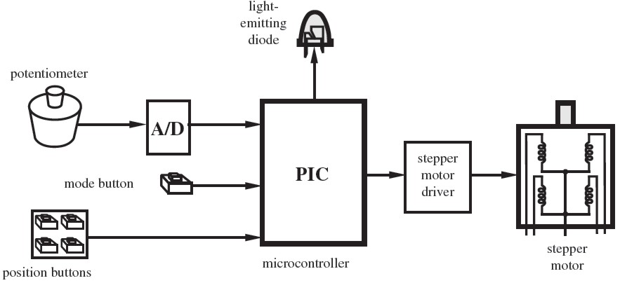
Figures Introduction To Mechatronics And Measurement Systems
Difference Between 4 Wire 6 Wire And 8 Wire Stepper Motors
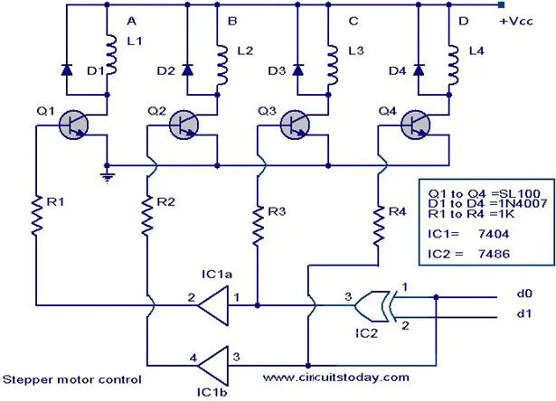
Stepper Motor Controller Driver Circuit With Circuit Design
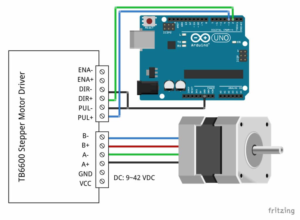
Tb6600 Stepper Motor Driver With Arduino Tutorial 3 Examples

Electronic Circuit Schematic Of Stepper Motor Driver Cw Is 1010
