Temperature Wiring Diagram

Controlbyweb Temperature Sensor For Controlbyweb Products
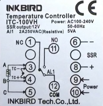
Pid Inkbird Itc 100vh Wiring Usage Overview
How To Build On Off Temperature Control Circuit Diagram
Stc 1000 temperature controller wiring diagram 05062019 05062019 4 comments on stc 1000 temperature controller wiring diagram growing tired of swamp cooling for fermentation temperature control in the widely popular 2 stage stc ebay temperature controller.
Temperature wiring diagram. See how it all ties together in the ecm engine control module. A common version is the constant current circuit shown here. Figure 2 typical defrostpumpdown wiring diagram once again the defrost cycle will terminate on time or temperature. 4 wire rtd circuits not only cancel lead wires but remove the effects of mismatched resistances such as contact points.
It reveals the elements of the circuit as streamlined forms and also the power and also signal links between the tools. Collection of pid temperature controller wiring diagram. Wire gauges in series from a positive temperature. Collection of temperature controller wiring diagram.
You can save this image file to your individual computer. This is the temperature gauge wiring diagram 1957 chevy temperature gauge of a pic i get coming from the engine temperature gauge wiring diagram collection. A wiring diagram is a simplified traditional pictorial representation of an electrical circuit. Learn the electronics of the engine coolant temperature sensor.
Fan delay can be accomplished by either a temperature control thermostat or klixon or a time delay. The engine coolant temperature ect sensor responds to change in engine coolant temperatureby measuring engine coolant temperature the ecm engine control module knows the average temperature of the engine and tells the computer what the engine temperature is so that optimum driveability is realized while the engine is warming up and when the engine has reached operating temperature. It reveals the components of the circuit as streamlined shapes and the power and also signal connections in between the devices. Ect sensor wiring diagram amazon printed books https.
A wiring diagram is a simplified standard photographic representation of an electric circuit. Air mix door control. Please right click on the image and save the graphics. Electronic automatic temperature control wiring diagram of 2001 nissan quest v41 2001 nissan quest v41 series electronic automatic temperature control eatc system feature.
Needle to the temperature of the engine waterusing the expertise weve gained in developing specialized solutions for many of the worlds leading manufacturers we offer a large portfolio of pressure.

Smart Cooling Fan Circuit
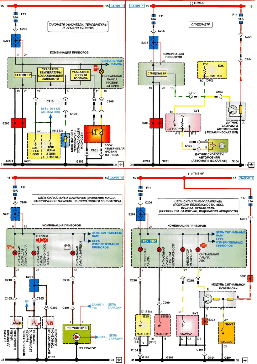
Daewoo Lanos Wiring Diagrams Car Electrical Wiring Diagram
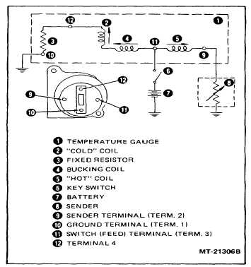
Figure 19 Water Temperature Gauge Circuit Diagram

Level Sensor Temperature Rosemount Inc Wiring Diagram Others
Two Wire Temperature Sensor Circuit Diagram

How To Replace Broken Wire Harness Clips Or Connectors On Audis
Complete Circuit Diagram Of Temperature Control System Two

B6a Water Temp Gauge Wiring Diagram Wiring Library

Two Ways To Measure Temperature Using Thermocouples Feature
