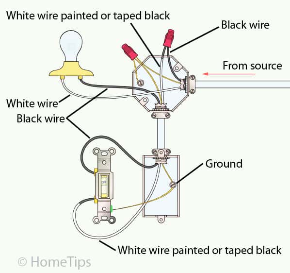
Three Wire Electrical Switch Diagram
With these diagrams below it will take the guess work out of wiring.

Three wire electrical switch diagram. Featuring wiring diagrams for single pole wall switches commonly used in the home. Explanation of wiring diagram 1. Wiring a 3 way light switch is certainly more complicated than that of the more common single pole switch but you can figure it out if you follow our 3 way switch wiring diagram. Wiring a 3 way light switch.
Now discussing 3 way light switch wiring diagram as also discussed above the color codes of the wires as having three insulated conductors as black as hot red as switch wire or called traveler and white as common wire as also shown when light is connected to both black and white wires. Knowing how to wire a three way lighting switch comes down to understanding the operation of this contraption. In the 1st diagram below a 2 wire nm cable supplies power from the panel to the first switch box. In this diagram the electrical source is at the first switch and the light is located at the end of the circuit.
This might seem intimidating but it does not have to be. Video includes the bonus addition of adding a 4 way switch. Switch wiring shows the power source power in starts at the switch box. Typical 3 way switch wiring nm cable.
Below is a simple schematic diagram that can be applied to all three way electrical light switch connections. Take a closer look at a 3 way switch wiring diagram. With a pair of 3 way switches either can make or break the connection that completes the circuit to the light. 3 way switch wiring diagram with power feed via light.
A 3 wire nm connects the traveler terminals of the first and second 3 way switch together. A three way switch is fundamentally different in its operation from a regular two way switch. Wiring diagram 3 way switch with light at the end. The electrical system consists of the line from the pole a meter where electrical usage is tallied a main circuit breaker panel sometimes called load centers and in older homes fuse.
On the other three way switch the load wire the load is the wire that feeds power to the light fixture gets connected to the copper or black screw terminal. A 3 way switch circuit is explained and described in detail including visual animation and practical application. The black and red wires between sw1 and sw2 are connected to the traveler terminals. Three wire cable runs between the switches and 2 wire cable runs to the light.
You must completely forget about the notion of a switch being a simple openclosed circuit and look at the diagram of the circuitry of this modern alternative. How to wire a single switch. Interested in a 4 way switch wiring diagram.