Tilt Sensor Wiring Diagram

Do I Need To Solder Wires To My Tilt Sensor Arduino Stack Exchange
Tilt Sensor Types Working Principle And Its Applications

Gl 3000 Simple Motion Sensor Circuit Free Diagram
Mercruiser trimtilt wiring for the position sender the diagram shows one side to ground and the other side to a brownwhite wire that goes to the connector and on up to the trim gauge.

Tilt sensor wiring diagram. All music available at http. Question from a fellow boater. Look on the back of the gauge and see if there is a brw wire there. Family marine 490422 views.
Connect the components based on the figure shown in the wiring diagram using a m m pin connector. Alasdair just had a look at the wiring diagram looks like the tilt sensor is called the gradient monitor and is the box at the bottom of the diagram and the plugsocket is x1222. Tilt sensor module 1 pin m m connectors breadboard usb cable 1. Circuit diagram in this sensor two conducting poles placed and the mass roller placed between these two pole elements.
Amazon evinrude johnson oem johnsonevinrudeomc trim seal o amazon evinrude johnson oem johnsonevinrudeomc trim seal oring repair kit 434519 0434519 sports outdoors. Volvo penta tilt trim diagram. It reveals the parts of the circuit as simplified shapes as well as the power and also signal connections between the devices. Hope this helps.
Learn about propellers be a hero not a zero propeller for sale st cloud minnesota boat dealer duration. The part numbers for the relay housing show that they. Wiring the mercury type tilt sensor in this illustration we will going to wire the mercury switch module is a family of the tilt switching sensor and it has an on board led as indicator as power status it can be used to build a simple circuit to produce tilt warning. And here is the colour code for the wiring.
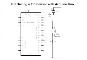
The purpose of these trim tilt relays is to activate and reverse the current flow so the motor can spin in two directions allowing the outboard to go up and down. A wiring diagram is a streamlined traditional photographic depiction of an electric circuit. Collection of mercury outboard wiring diagram. Here we interfaced tilt sensor with arduino board and led as output indicator remember to connect 10kw bias resistor between ground gnd and one terminal of tilt sensor that is connected to arduino digital input pin.
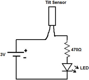
A tilt sensor is a sensor which opens and closes an electrical circuit when it is inclined beyond at certain angle. Vcc pin is connected to the 5v power supply gnd pin is connected to the gnd and the out pin is connected to the digital io pin.

Inventas Electronics How To Use Tilt Sensor With Arduino Uno

Zct260al 485 Low Cost Anti Vibration Rs485 Digital Tilt Sensor For
Anti Theft Alert System Using Atmega8 Microcontroller And Tilt Sensor
Inventas Electronics How To Use Tilt Sensor With Arduino Uno

Sensor Wiring Connection Problems Solved Jewell Instruments
Yamaha Yzf R125 Service Manual Checking The Lean Angle Sensor

Av 0347 Optomechanicaltilt Sensor Principle Of Operation Free Diagram

Wiring The Mercury Type Tilt Sensor 14core Com

Tilt Click Board With Rp 1035 4 Directional Optical Tilt Sensor
