Toyotum Oxygen Sensor Wiring Diagram
Fx5 Jb87m8umym
Honda 4514 Wiring Diagram Schematic Boat Wiring Diagram Typical

Diagram Based Mustang O2 Sensor Wire Diagram 4 Completed
Building circuitry diagrams show the approximate locations and also affiliations of receptacles illumination and also permanent electric solutions in a structure.
Toyotum oxygen sensor wiring diagram. The sensor detects oxygen levels in the exhaust gases and sendsthis signal to the ecm. On the sensor you should be able to measure somewhere between 6 8 ohms between two of the wires which go to the heater. The oxygen or o2 sensor reads the percentage of oxygen in the exhaust coming from the engine and sends this information to the computer. Learn about the o2 sensor electrical connection and how it relates to the ecm and signal output.
Heated oxygen sensor bank 1 sensor 2 evp1 br 2 ee1 br ptnk 7 3. The o2 or oxygen sensor is in charge of measuring the content of the exhaust. For the purpose of helping the ecm to deliver accurate air fuel ratio control a heated oxygen ho2 sensor is used. It shows the components of the circuit as simplified forms and also the power as well as signal links in between the devices.
A wiring diagram is a simplified standard pictorial representation of an electric circuit. This maximizes the catalytic converters ability to purify the exhaust gases. If an o2 sensor fails the engine will not run properly. The computer can then determine if the engine is running rich or lean.
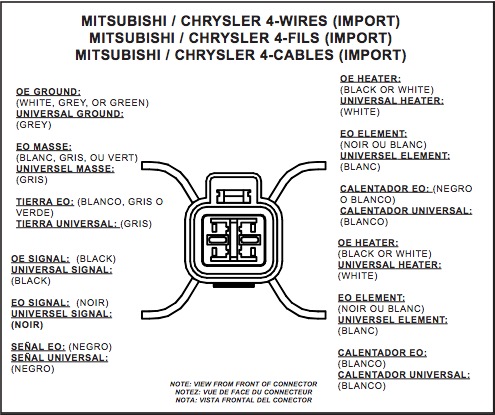
Assortment of oxygen sensor wiring diagram. 4 wire oxygen sensor wiring diagram fresh audi a4 oxygen sensor. Youll probably need to check the wiring diagram to find which wire colors are for 12 ground and the input but if you can find the ground and 12 wires for the heater with a meter then the one thats left is the input. The engine control module ecm uses the heated oxygen sensor information to regulate the airfuel rationear to the stoichiometric airfuel ratio.
When the ignition sw is turned on and the brake pedal is pressed stop lamp sw on if the stop light circuit is open the current flowing from terminal 7 of the light failure sensor to terminals 1 2 changes so the light failure sensor detects the disconnection and the warning circuit of the light failure sensor is activated.

2001 Lexus Gs 300 Engine Scematic Diagram Tuli Fuse19 Klictravel Nl

Jeep O2 Sensor Wiring Diagram Diagram Base Website Wiring Diagram

Toyota 02 Sensor Wiring Diagram Wiring Diagram

How To Check And Replace An Oxygen Sensor Air Fuel Ratio Sensor
5 Wire O2 Sensor Wiring Diagram

Lexus Rx300 Knock Sensor Wiring Diagram Auto Electrical Wiring

Qgolglr5uc0vzm

2004 Honda Odyssey Bank 1 Sensor 1 Location

O2 Sensor Heater Quick Fix Youtube
