Tsubaki Wiring Diagram
Selecting a given series is a matter of preference based upon the features and benefits.

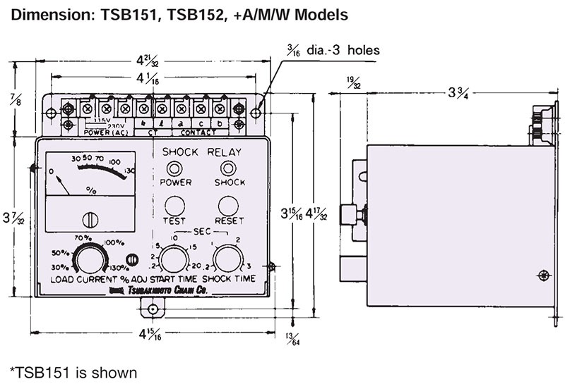
Tsubaki wiring diagram. Protect your equipment and investment with tsubaki shock relays and external current transformers. Do not bend pull or pinch the power cable or motor lead wires otherwise electrical shock may occur. In case of no terminal box insulat e terminals completely. Shock relay with the simple wiring system this current detecting overload protection device can swiftly detect motor overcurrent and output a signal causing an emergency stop to prevent your equipment from damage.
That means high maintenance costly repairs and. Instruction manual tsubaki em warning make sure you read this instruction manual thoroughly before installing wiring operating and inspecting this shock relay please make sure that this instruction manual accompanies the shock relay to the end user. Be sure to open the arms when connecting. Ct wiring shock tsasb05 tsasoos tsasgos tsasb05 tsasbm tsasb60 tsasa60 tsaseos tsosaos tsasbio tsasb30 tsasa30 relay.
The tsubaki cableveyor may be shipped in sections depending on packing and shipping considerations. In case of no terminal box insulate terminals completely. It carries many attractive features and comes in a wide range of models that meet the needs of customers. As seen below these three attributes are used to select the correct size range.
3 push in the other side. Browse tsb151 tsb152 shock relay for overload protection in the us. 2 overlap the links and insert the pins so they all face one direction. The tsubaki power lock has been highly acclaimed since its introduction into the locking device market.
Wiring if you do not connect the power cable according to the wiring diagram shown in the terminal or this instruction manual electrical shock or fire may occur. Catalog including item motorload current rangeinput voltage for operationsurface colorweight. 1 match the proper direction. Unexpected shock loads can damage chains drives gears turbines the entire mechanical assembly.
Basic connection diagram dip switch selection set to ss o externally mounted ct type tsbsbioo tsbsb200 dip switch selection set to sa o to relay shock cts 3 va va dip. Contents selection guide 1 34 selection guide 2 56 selection guide 3 78 application examples 911 as series 1222. Connect the sections to the desired length as per the following steps. Wiring if you do not connect the power cable according to the wiring diagram shown in the terminal or this instruction manual electrical shock or fire may occur.
Product specification is subject to change for improvement without. The most important aspect of ordering a tsubaki shock relay is knowing the electric drive motor horsepower voltage and amperage rating.