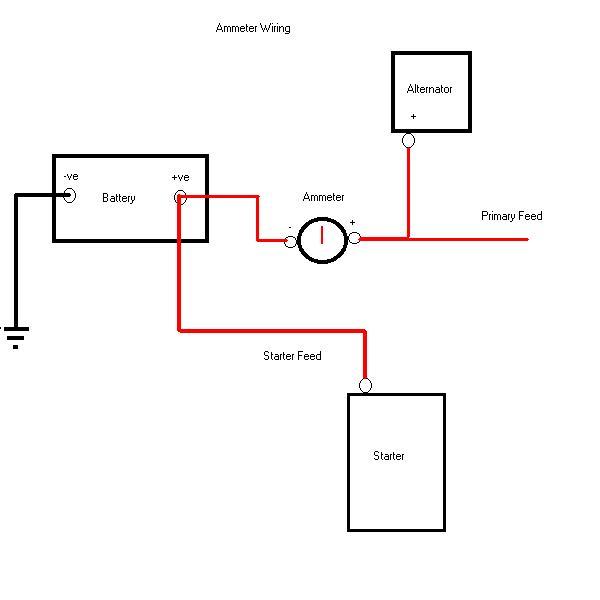
Typical Alternator With Amp Meter Wiring Diagram
Testing Battery And Charging System
How To Test A Bmw E39 Battery Alternator Discussion By Bluebee
Ebe5572 Amp Meter Wiring Diagram For Ford Wiring Library
Amp gauge wiring 1 always disconnect the ground lead from the vehicle battery before wiring any gauge.
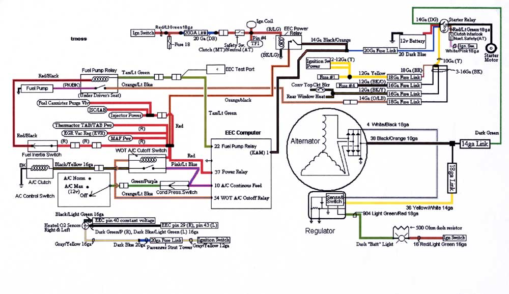
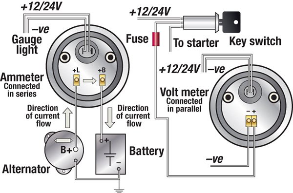
Typical alternator with amp meter wiring diagram. However the majority of alternators have three or four terminals which wires connect to. This video describes the procedure for converting your automotive generator based charging system to an alternator based system. Collection of delco 3 wire alternator wiring diagram. Model a ford wiring keeping the current flowing.
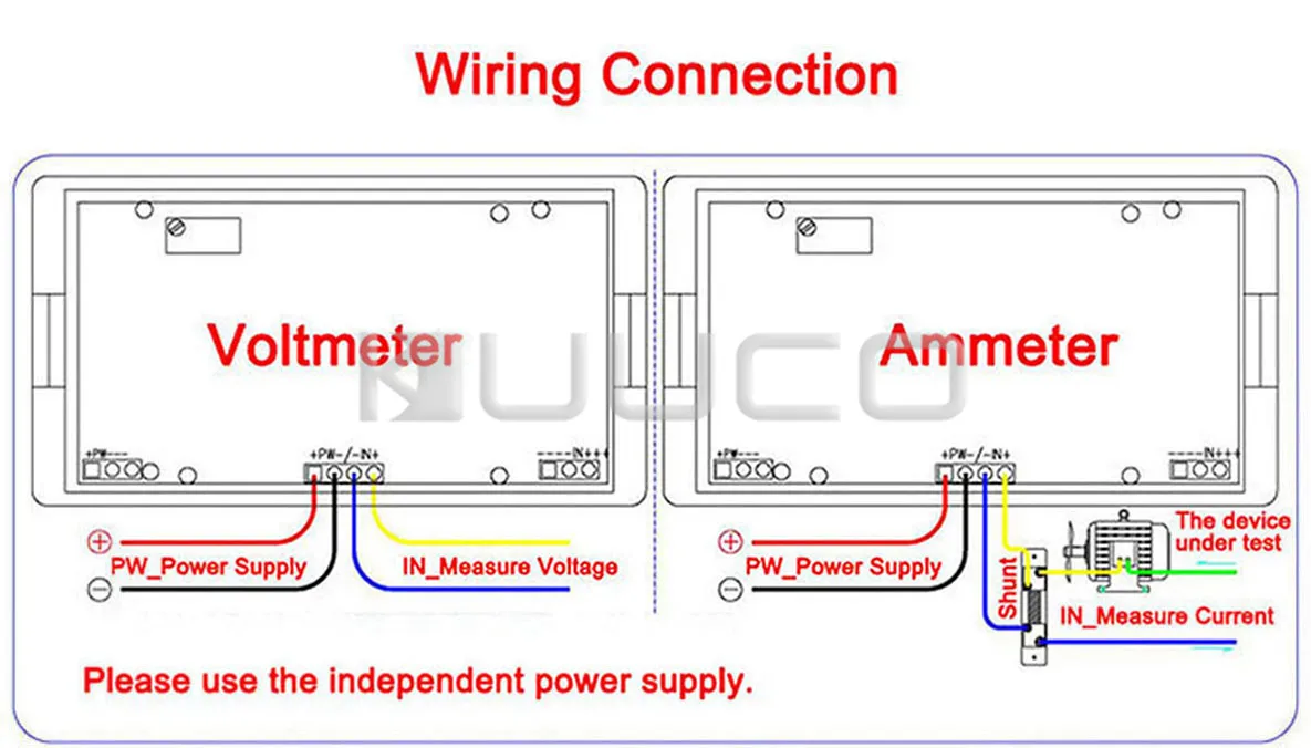
Assortment of volt amp meter wiring diagram. 800 x 600 px source. Checking typical alternator wiring is a moderately easy task. A wiring diagram is a simplified conventional photographic depiction of an electric circuit.
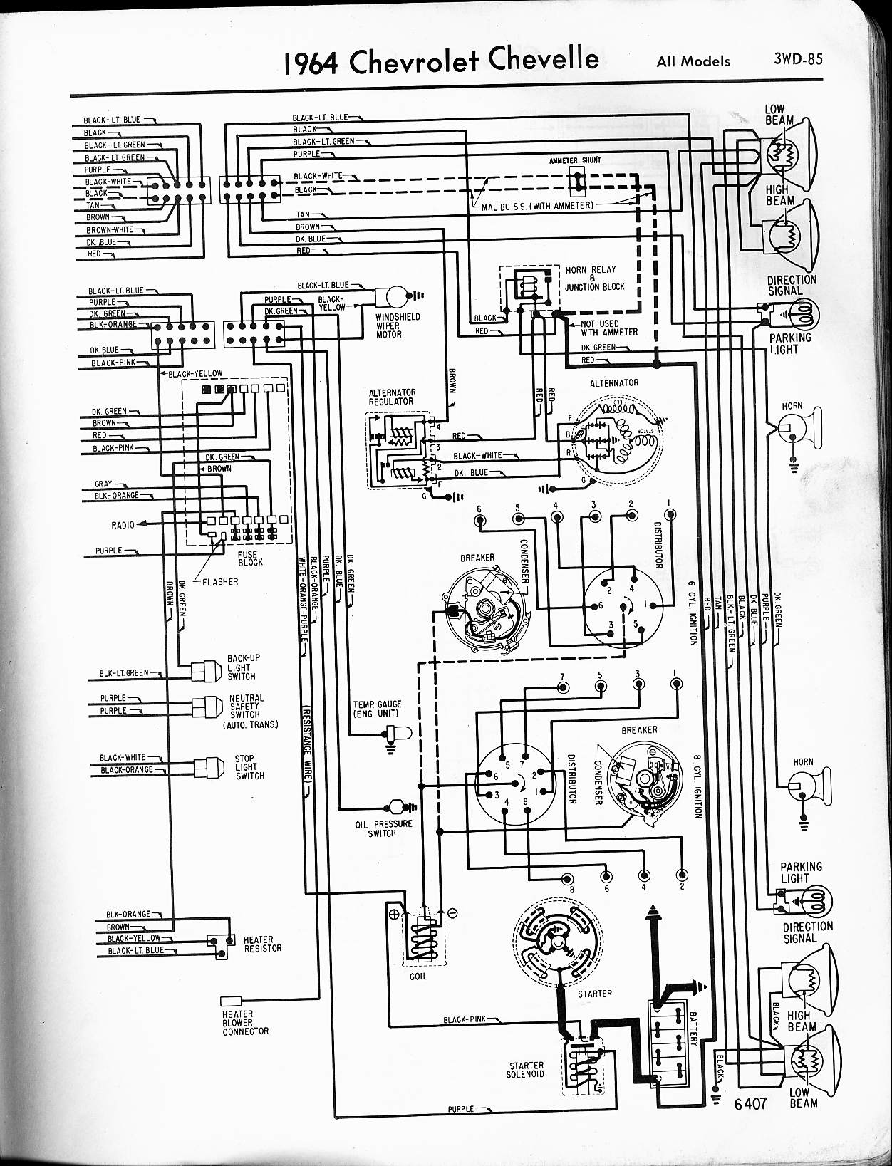
1 wire vs 3 wire alternator plus other tips for classic cars muscle cars episode 260 autorestomod duration. 2 classic instruments amp gauge should only be used on vehicles with alternators rated at 60 amps or less. It reveals the elements of the circuit as simplified forms and the power and signal connections between the devices. 8n 12 volt conversion wiring diagram.
Step 10 start engine and test alternator. Using an alternator with higher output capacity is dangerous and could cause a fire. Autorestomod manic mechanic gasoline media 212808 views 1703. Typical wiring diagram without cowl lamps beginning in february 1929.
You can also check the amp volt meter by. This happens to be a 1962 willys cj 5 that we are working on but. Some modern alternators only have one wire as all the external functions are housed within the alternator and as the alternator is fixed to the car engine this completes the ground circuit. Your alternator is working when you can feel a magnetic pull on the knife or screwdriver.
The standard 3 point lift arm spheres need to reduce to regarding 8 12 over the ground as well as an increase to about 34 14. Right here are some of the leading drawings we get from various sources we wish these pictures will work to you and also ideally extremely appropriate to what you want about the 1 wire alternator wiring diagram is. Dash wiring to terminal box harness amp meter discharge side igniton switch amp meter charge side. A wiring diagram is a simplified traditional photographic representation of an electric circuit.
Gauging voltage is one of the most typical examinations a tractor auto mechanic will conduct as he repairs a system. While engine is at idle take a screwdriver or pocket knife and place on the back of the alternator bearing surface the round area in the middle of the back of alternator.

780f Generator External Voltage Regulator Wiring Diagram Wiring

Automotive Amp Gauge Wiring Schematic Wiring Diagram

Prestolite Leece Neville
How To Wire A Voltmeter To An Alternator
Https Www Matec Conferences Org Articles Matecconf Pdf 2017 04 Matecconf Aigev2017 01076 Pdf

Gm Regulator Wiring Wiring Diagram
F52f7b9 Typical Alternator With Amp Gauge Wiring Diagram Wiring
Troubleshooting Boat Gauges Instruments And Meters Boatus
In Car Amp Meter
