Typical Motor Control Wiring Diagram
Ladder Diagram Engineering Expert Witness Blog
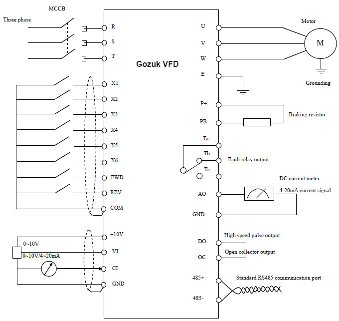
Variable Frequency Drive Working Principle

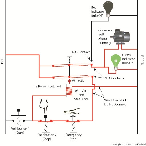
Basic Control Circuits
It is important to note.

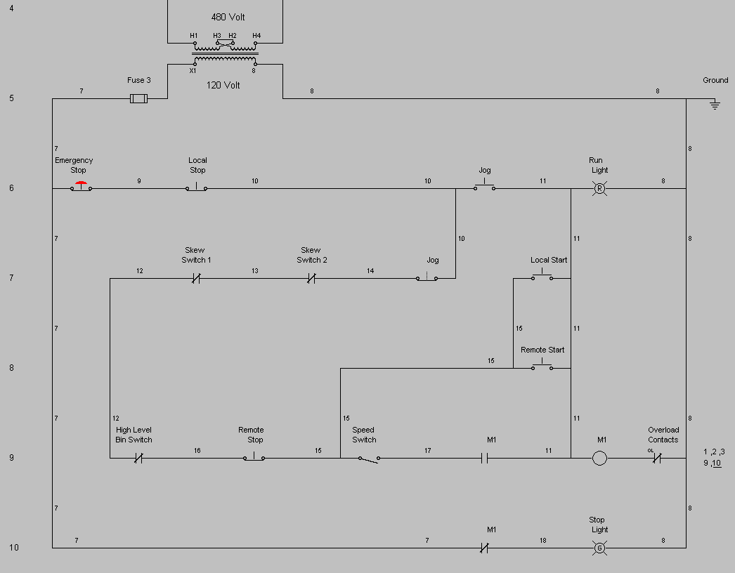
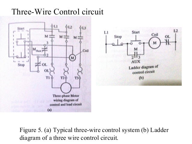
Typical motor control wiring diagram. Typical starter wiring diagram three phase. The diagram for a typical full voltage across the line starting circuit is shown in figure 1. Motor connection diagrams full lecture. Electric motor wiring diagram amazon printed books https.
The pro 150 is interchangeable with the pro 120 in most situations. Note the control circuit is a three wire ladder diagram control circuit which works well for smaller horsepower three phase motors. Unit 1 basic principles of motor controls unit 1introduction this unit discusses the basic concepts of motor control including motor control language and the types of wiring diagrams used. They show the relative location of the components.
Figure 1 typical wiring diagram. Detailed diagrams for each controller are contained in their respective manuals but here we have a typical dc motor speed control diagram showing the wiring for a pro 120 controller. In which one for forward. The symbols used in this booklet were.
The control circuit may not be at the same voltage as the power circuit. The dno and vtx ncc is almost identical but the tags are 63mm not 95mm. Basic wiring for motor control technical data. Figure 1 is a typical wiring diagram for a three phase magnetic motor starter.
A particular application must satisfy the needs of the user and comply with applicable codes laws and standards before using any of the typical circuits shown in this publication. Understanding of motor control wiring dia grams. The control circuit is separate from the motor circuit. In the video i explained the two 3 phase motor forward reverse starter wiring diagram.
This video is about the 3 phase motor reverse forward motor control circuit diagram. They can be used as a guide when wiring the controller. When the voltage of the control and power circuits is the same it is referred to as common control. This diagram shows both the power circuit and the control circuit.
If the volt ages are different it is called separate control.

Series Motor Speed Controller Circuit Diagram Electrical
017641 Electrical Wiring Diagram Schematic Symbols Motor Control
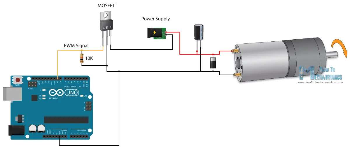
Arduino Dc Motor Control Tutorial L298n Pwm H Bridge
Motor Control

Electrical Wiring Diagram Forward Reverse Motor Control And Power
Basic Wiring For Motor Control Technical Data Guide Eep

Dc Motors And Stepper Motors Used As Actuators
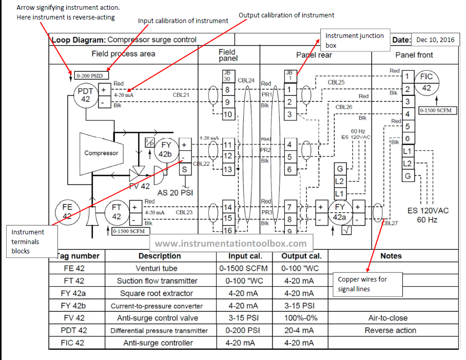
Basics Of Instrument Loop Diagrams Learning Instrumentation And

Motor Control Center Bucket Wiring Diagram Diagram Base Website
