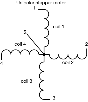
Unipolar Stepper Schematic
Unipolar And Bipolar Stepper Motors Youtube
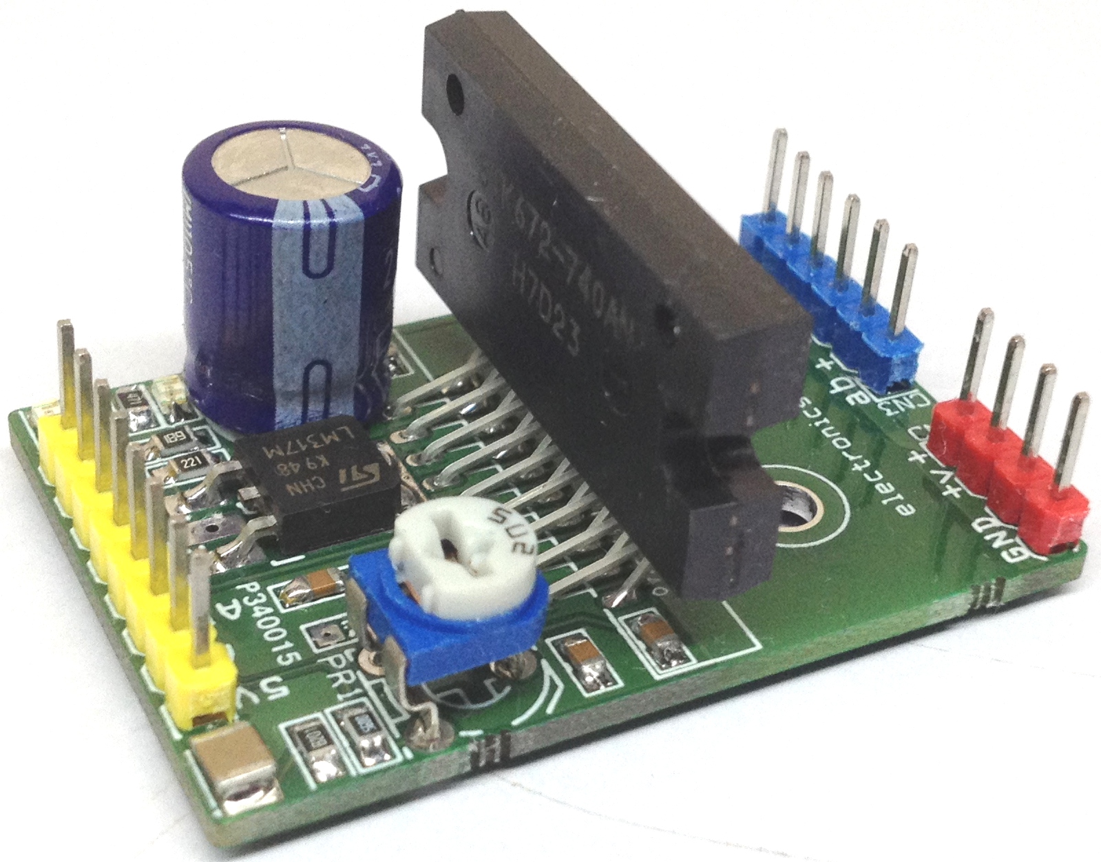
4a Pwm Controlled Unipolar Stepper Motor Driver Using Stk672 740
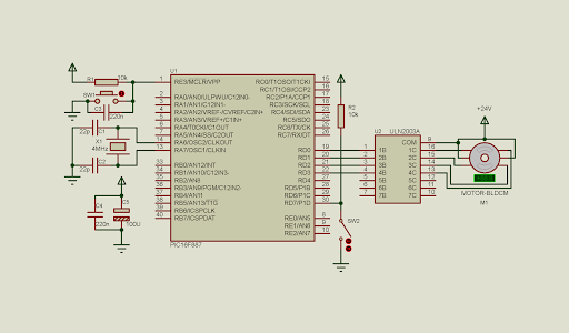
Diy Electronics Programming Tutorials Pic16f887 Interfaces To A
Interfacing pic16f877a with unipolar stepper motor ccs c code.
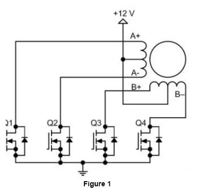
Unipolar stepper schematic. Unipolar stepper driver schematic with transistors you can power steppers from constant voltage supplies. The microcontroller reads the analog data from an0 and uses the digital value to change the delay between motor driving sequences. So here i present uni polar stepper library in arduino for all unipolar type stepper motors having 4 phases. The one we use has 6 connectors of which one is power vcc and the other four are used to drive the motor sending synchronous signals.
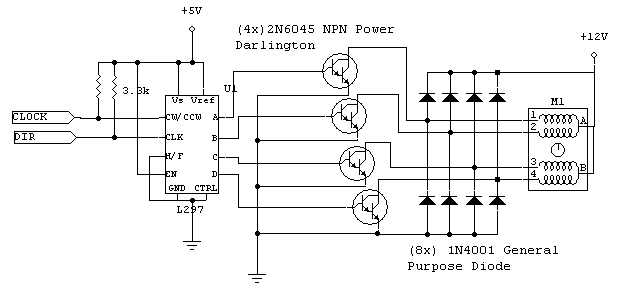
A pot connected to an0 is used to control the speed of the stepper motor. In the full step control mode always two windings are energized at the same time according to the following table where 1 means the coil is energized and 0 means not energized both directions are shown. The l297 has several inputs that can be generated by a pc104 stack or other controller. This unipolar stepper motor driver circuit is used to drive a 12v unipolar stepper motor with a current rating of 125a.
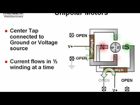
If you do not know how stepper motors work and how they are made what is unipolar and bipolar or what is full step half step and micro stepping i strongly suggest that you read first the theory page how stepper motors work and how they are made that i wrote a few months ago. So here i present a very simple and basic full step stepper controller for a unipolar motor. But a constant current supply is a better choice especially when you want good performance and you dont know motors voltage ratings. This page shows two examples on how to drive a unipolar stepper motor.
It uses pca9537 ic which is a 10 pin cmos device that provides 4 bits of general purpose io gpio expansion with interrupt and reset for i2c bussmbus applications. Since in this arrangement a magnetic pole can be reversed without switching the direction of current the commutation circuit can be made very simple eg. In this example im going to use the uln2003a or uln2004 chip. The library has 9 different functions that can be used to rotate and control motor as per the requirementsthe library is design as per the industrial motion control requirements.
The unipolar stepper motor can be driven with l293d motor driver or uln2003a darlington transistor array ic. These motors can be found in old floppy drives and are easy to control.

Sending Pulse An Overview Sciencedirect Topics
Stepper Motor Driver Circuit Ato Com
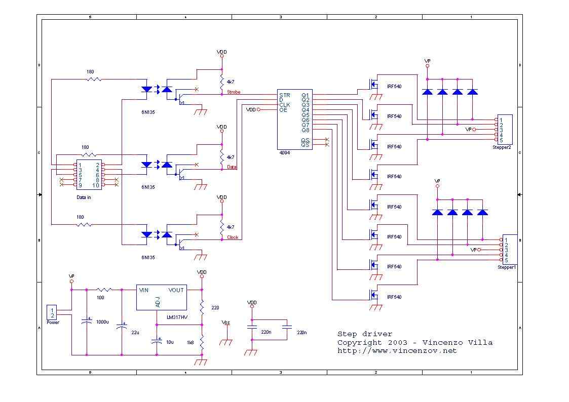
6n135 Isolated Unipolar Stepper Motor Driver Circuit Electronics

Ede1200 Unipolar Stepper Motor Driver

555 Timer Stepper Motor Controller Circuit
Stepper Wiring Unipolar Itp Physical Computing
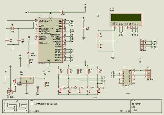
Unipolar Stepper Motor Control Circuit With Pic16f877
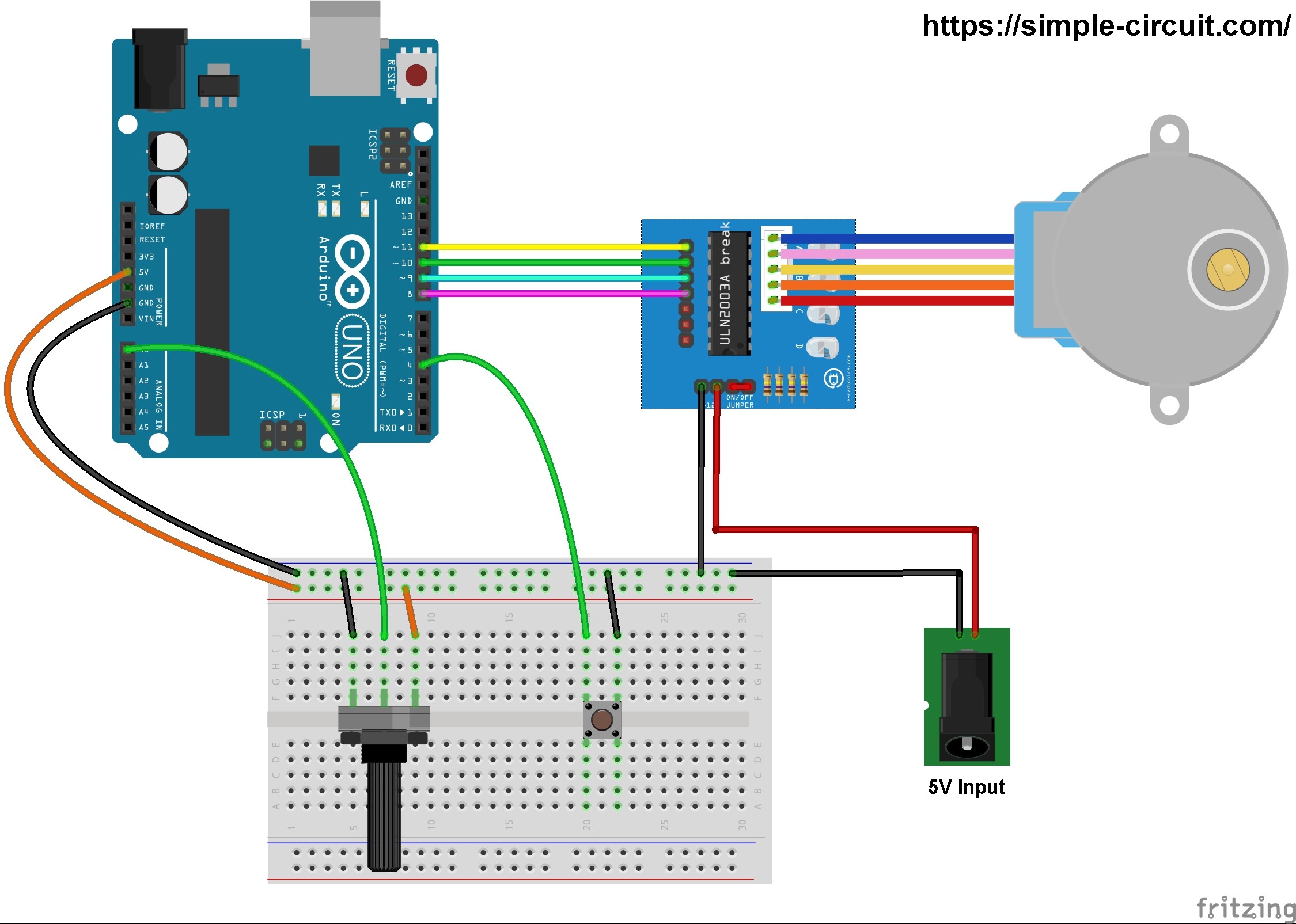
Arduino Unipolar Stepper Motor Control Simple Projects
Arduino Unipolar Stepper Motor Control
