Up Control Wiring Diagram

Mitsubishi Mirage Forum Also G4 Sedan Space Star Attrage Dodge

E Bike Controller Wiring Diagram Canopi Me For Electric Bike
9continent 48v 40a Controller Wiring Up Endless Sphere
Ups inverter wiring diagram with auto manual changeover switch system.
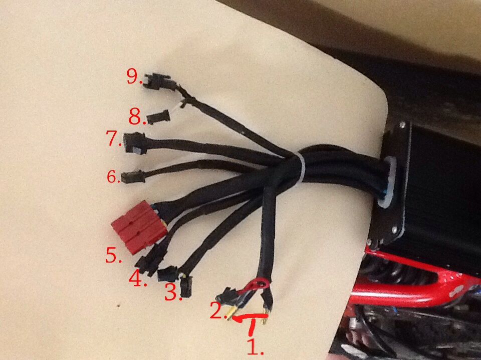
Up control wiring diagram. 40 literature. Now according to the below ups connection diagram connect an extra wire phase to those appliances where we have already connected phase and neutral wires from power house db ie two wire as phase live as shown in the below fig. This harness wiring diagram shows how to match up the wires for each connection to the wiring harnesses. A wiring diagram is a streamlined standard pictorial representation of an electrical circuit.
Create an electrical wiring diagram to display wire connections and the physical layout of an electrical system or circuit. Ensure it is sealed off and cannot create a short circuit with any other wire or the chassis. Assortment of rainbird sprinkler wiring diagram. Nlight control system installation worksheetnlight project installation form.
A wiring diagram is a simple visual representation of the physical connections and physical layout of an electrical system or circuit. Control wiring 3 wire control start stop circuit the most common use of 3 wire control is a startstop control. Within a typical nlight network multiple zones are wired individually to a bridge. The service brake circuit must be disconnected from an existing trailer plug.
This video demonstrates how to make reverse forward motor starter. See image below for an example of 3 wire control being used to pull in a contactor to start a 3 phase motor. Wiring diagram examples 1. Elecbrakes must be connected to trailer wiring circuits as outlined in the wiring diagram.
Related electrical wiring tutorial. This video is a step by step explanation of wiring start stop basics. In a room or area that are daisy chained wired together with cat 5 cabling. This is the first of many motor control.
It reveals the components of the circuit as streamlined shapes as well as the power as well as signal links between the devices. Get a custom drawn guitar or bass wiring diagram designed to your specifications for any type of pickups switching and controls and options. This video covers both power wiring and control wiring along with testing at the end of video using motor run status. As long as you follow the ladder diagram and take it one wire at a time its simple.

Unique Electric Brake Controller Wiring Diagram Australia With
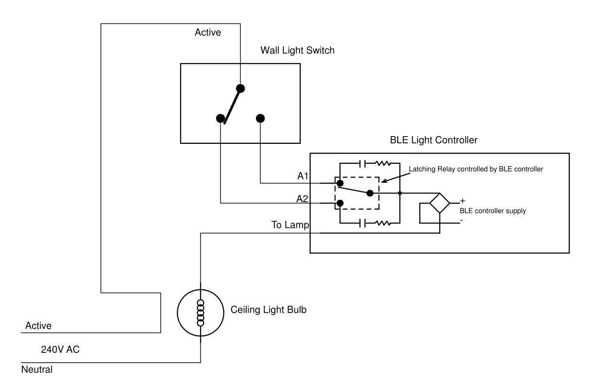
Remote Controlled Light Switch Retrofit With Manual Override
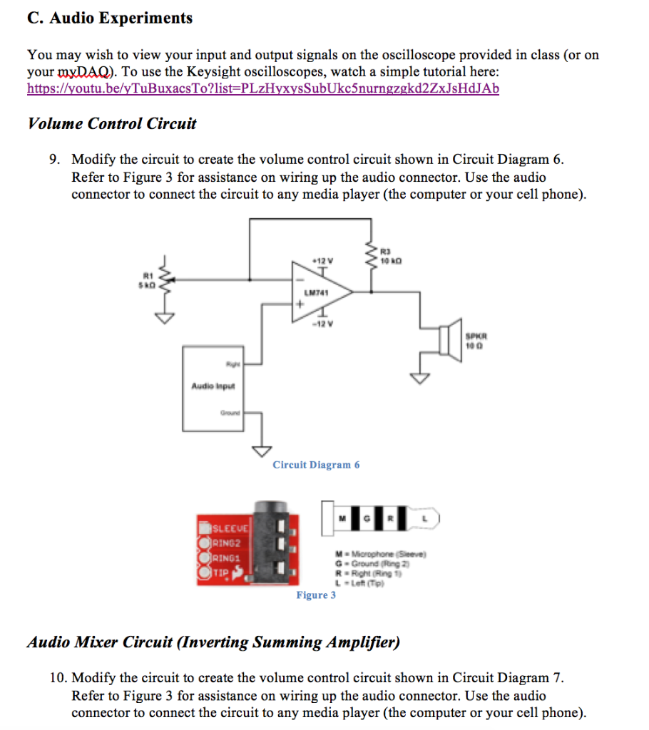
Solved C Audio Experiments You May Wish To View Your Inp
Advance System Connection Defi Exciting Products By Ns Japan

Single Axis Pulse Generator Stepper Controller Wiring Diagram
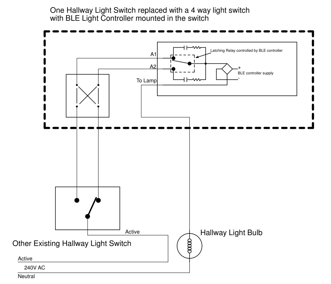
Remote Controlled Light Switch Retrofit With Manual Override
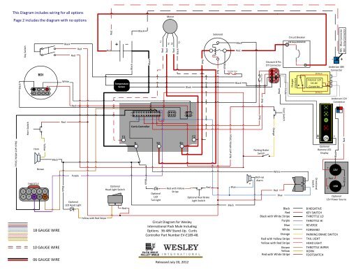
Wiring Diagram For 36 48v Stand Up Models With Curtis Controller

Technical Wiring Diagrams Louvretech Nz Louvretec

Reverse Motor Starters
