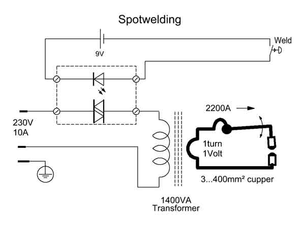
Welding Cct Diagram
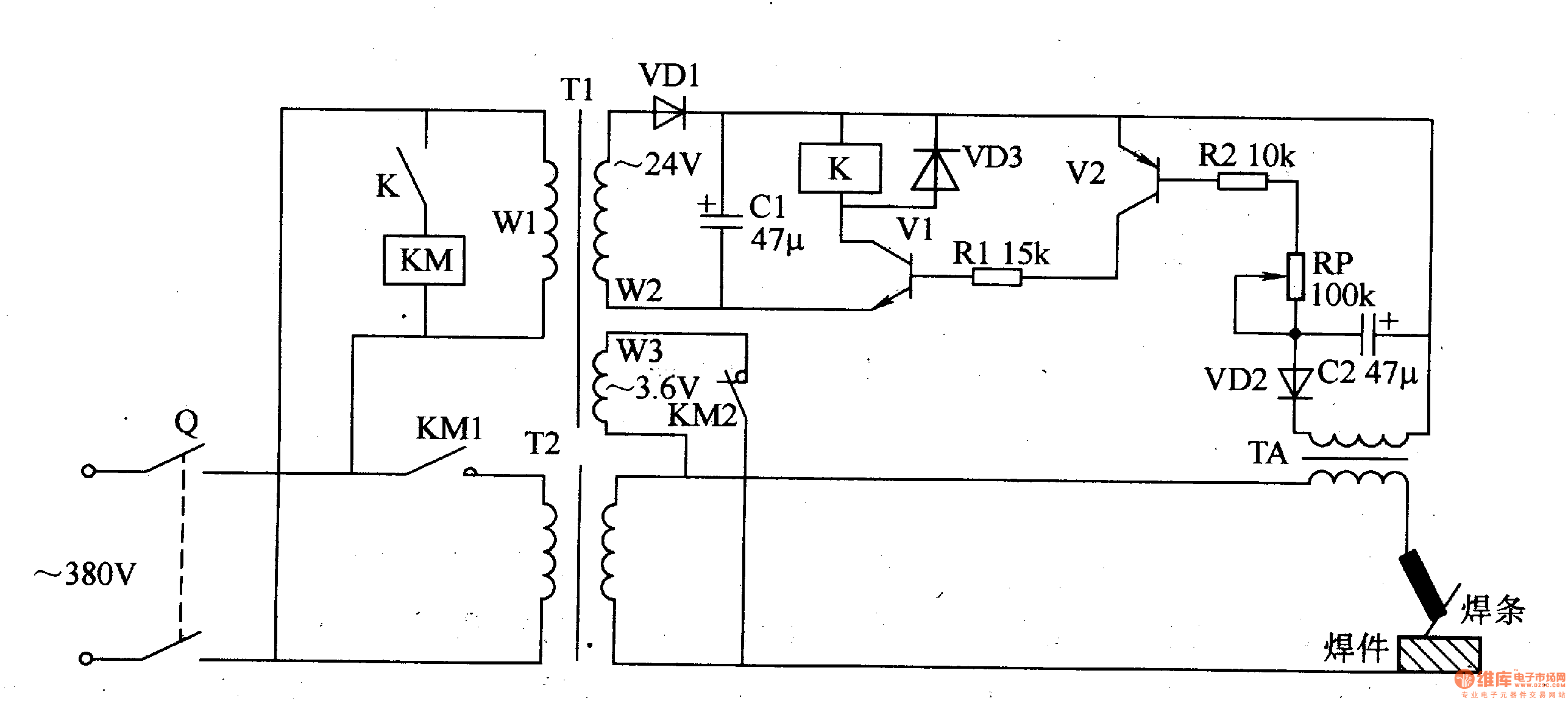
Electric Welding Machine No Load Electricity Saver 11
How To Modify The Cp 250ts For Single Phase And Short Arc Welding
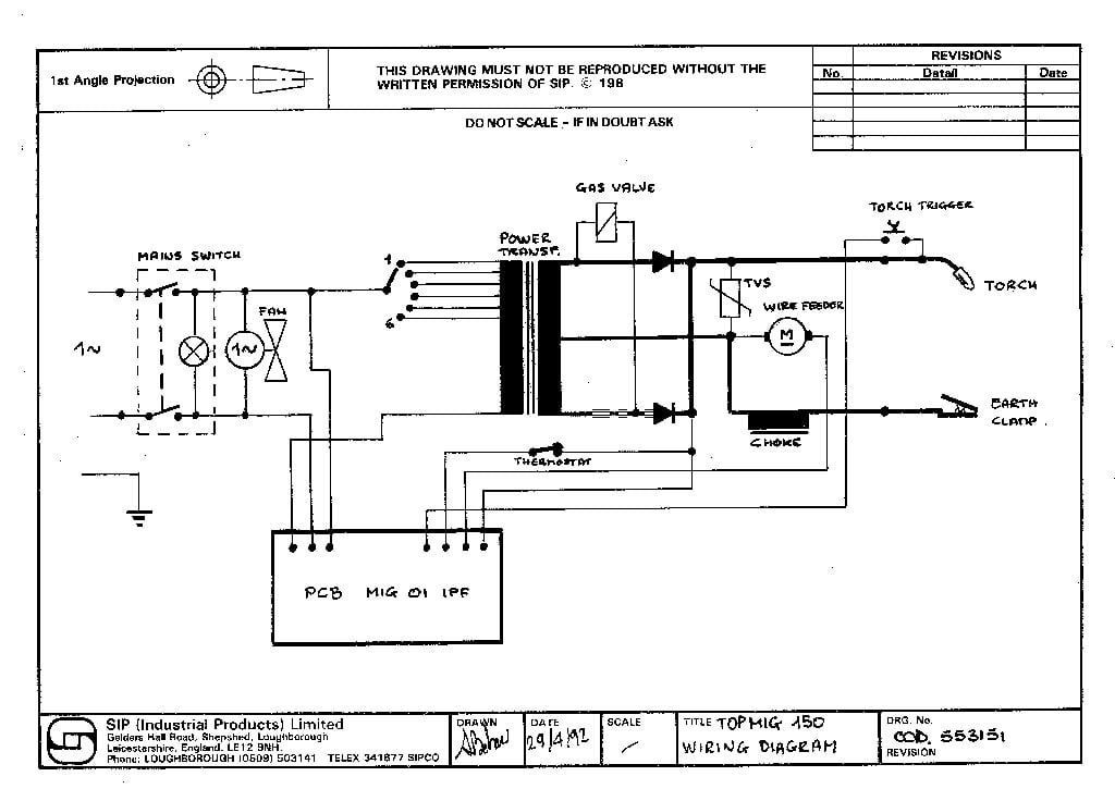
Sip 02591 Topmig 150t Circuit Diagram
Cct are continuous cooling transformation diagrams.

Welding cct diagram. There are many factors which control the properties of the weld metal and heat affected zone haz while welding of carbon. A dilatometer was built for this purpose. A continuous cooling transformation cct diagram is more appropriate to be used to predict the microstructures in the haz. Not shown in this demo version.
Ing transformation cct diagram valid for the heat affected zone haz in welding operations with rel atively rapid heating up to about 1200oc on an offshore pipeline steel of x70 type has been established along with the linear thermal expansion co efficients for the austenite and bainite phases. After welding the weld pool will surely reach a1 temperature and the given conditions for cooling of the weld pool deci. Cct and ttt are the diagrams which shows the variation in microstructure resulting after cooling with different cooling rates. These diagrams are used to represent which types of phase changes will occur in a material as it is cooled at different rates.
Ttt diagrams are time temperature transformation or isothermal transformation diagrams. A continuous cooling transformation cct phase diagram is often used when heat treating steel. It depends on type of cooling. Difference between ttt and cct diagrams.
This diagram is not a unique diagram like ttt diagram for a material. Circuit diagram of mig welding related poststypes of welding process everyone should knowwhat is underwater welding and how it workswhat is welding defects types causes and remedieswhat is seam welding and how it worksdifferent welding equipment and its functionwhat is forge welding and how it works. Heat affected zone and weld metal properties in welding of steels. These diagrams are often more useful than time temperature transformation diagrams because it is more convenient to cool materials at a certain rate temperature variable.
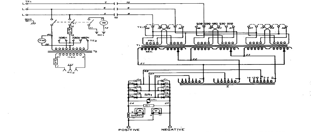
3000 us buy online transformation diagram other steel data links carbides in steel etchants database hardenability diagrams of steels macro defects in steel non metallic inclusions in steel tempering diagrams of steels cct and ttt diagram. Sh cct diagrams for welding and continuous cooling transformation behaviour for ductile cast iron takeshi nakata department of material engineering shibaura institute of technology shibaura 3 9 14 minato ku tokyo 108 japan correspondence nakataatsicshibaura itacjp. Cct diagram database cctd outline. The welding database system to predict hardness and microstructural constituents in the heat affected zone and to determine optimum welding conditions has been developed by using an estimated thermal cycle and the database of cct diagram for welding.

Welding Schematic Diagram Wiring Schematic Diagram Www Diddlhausen
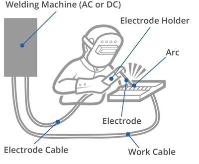
What Is Arc Welding Definition And Process Types Twi
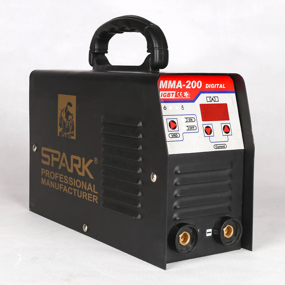
Best Price Mma 160 Mma 200 Welder Machine Circuit Diagram Inverter

Gas Metal Arc Welding Wikipedia
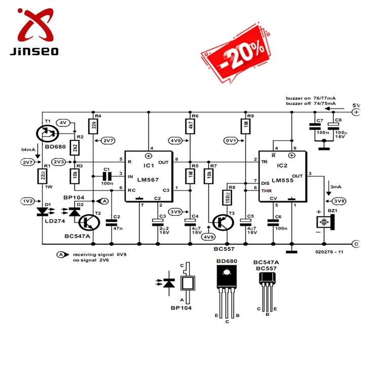
94v0 Pcb Electrical Circuit Diagram Of Welding Machine Design

Ez 0741 Welding Ttt Diagram Schematic Wiring
Welding Schematic Diagram Wiring Schematic Diagram Www Diddlhausen
Cct Curves And Welding

Air Over Oil Welding Tip Control By Proportion Air
