Wiring Diagram 5 Pin Midi
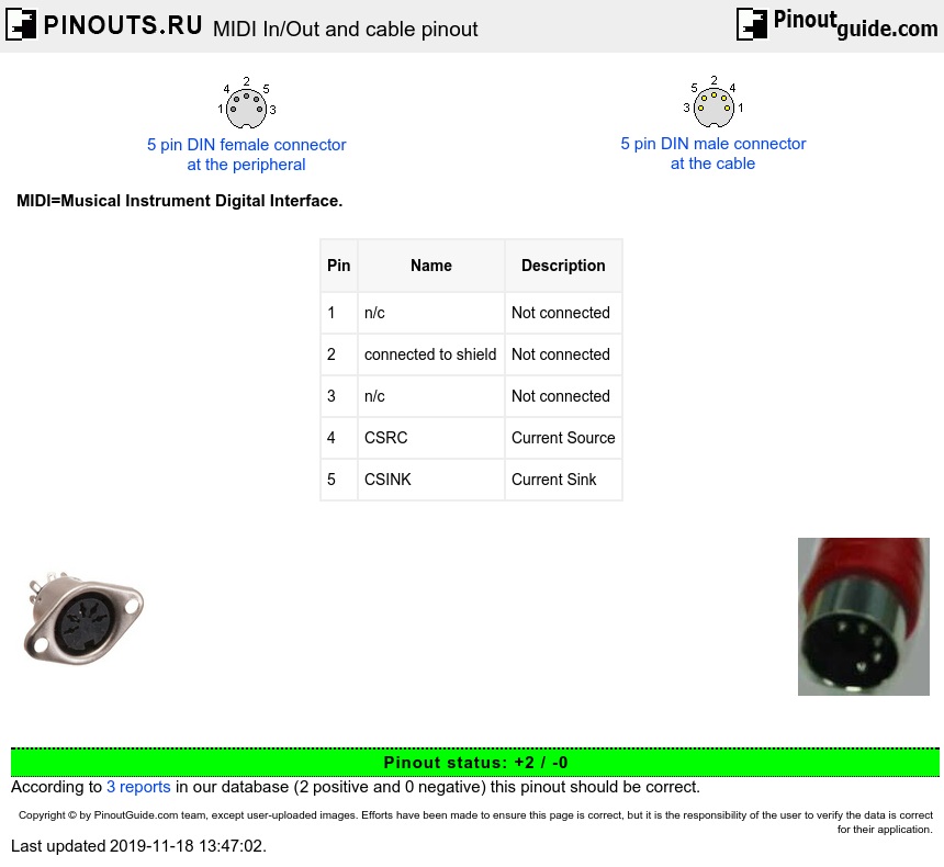
Midi In Out And Cable Pinout Diagram Pinouts Ru

4gmzwpom3uu Zm
Diy Do It Yourself
Spacing for easy.

Wiring diagram 5 pin midi. The signal on pin 5 is the current sink which is normally switched with the midi signal. There really is no 15 pin d defined in the current motherboard standards used as a game port. After soldering the wires to the pins of the plug do your best to clean off the solder flux with a suitable solvent. The cable should be screened with an overall lap screen.
5 pin midi wiring. This diagram is superceded by midi 10 electrical specification update 2014. Midi cables use a 180o 5 pin din connector with a single locating lug in the body but only uses three of the pins. The game port is usually integrated with a pc io or sound card either isa or pci or as an on board feature of some motherboards.
The joystick connector is found on sound cards. Pin 2 is used for the shield in order to ground the cable. This is a image galleries about 5 pin midi wiringyou can also find other images like wiring diagram parts diagram replacement parts electrical diagram repair manuals engine diagram engine scheme wiring harness fuse box vacuum diagram timing belt timing chain brakes diagram transmission diagram and engine problems. For a midi out connection.
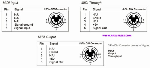
The midi port used with personal computers when found on sound cards uses a 15pin d connector the 15 pin midi connector has the following pin out. For more details please see the complete midi 10 detailed specification. How 35 mm tip ring sleeve mini jacks are wired to 5 pin din midi connectors it turns out that there are at least two different variations of wiring for trs to midi. Pin 4 ve or sink pin 5 ve or source for a midi in connection.
Midi electrical connections though midi for some reason standardised on din 5 pin sockets pins 1 and 3 are never needed. 5 pin din midi leads. The signal on pin 4 is the current source derived from a positive voltage in the driving midi output. Pinout of pc gameportmidi and layout of 15 pin d sub female connector and 15 pin d sub male connectorthe game port is the traditional connection for video game input devices on an x86 based pcs.
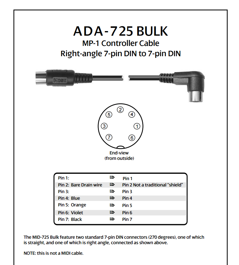
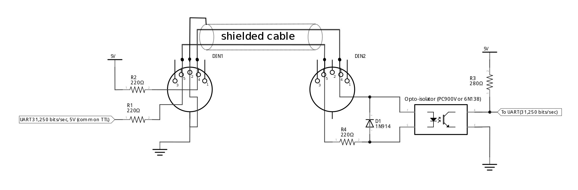
This kind of graphic leads direct din amp. The original circuit diagram is shown below for reference it is the most common circuit in use today and is still acceptable. That leaves the other two pins to carry an isolated current loop. Pin 2 is connected to the shield also known as screen or earth and the other pins are connected straight through.
Adafruit industries unique fun diy electronics and kits breadboard friendly midi jack 5 pin din id. We will call the main two trs type a and trs type b in this article. 1134 to celebrate the 30th anniversary of the invention of midi were carrying these handy 5 pin midi jacks. Original electrical specification diagram note.
From the thousands of images on the web concerning 5 pin din plug wiring diagram we selects the best selections using greatest resolution just for you all and this photos is usually one of images selections inside our greatest images gallery regarding 5 pin din plug wiring diagrami am hoping youll think its great. These are nice sturdy jacks and breadboard friendly with all the pins on 01quot.

How To Install The 5 Pin Din Male Solder Connector 180 Style
Scsi Wiring Diagram Hamra Arabians De

Odseven Breadboard Friendly Midi Jack 5 Pin Din Wholesale Od

26500 26
Midi Wikipedia

Hammer 88 Issue With Accent Module

How To Install The 5 Pin Din Male Solder Connector 270 Style

Wrg 6981 Midi Wire Diagram

Shavano Music Online Making Your Own Midi Cables
