Wiring Diagram For 1 Hp Motor

Wiring Harbor Freight 3 Hp Electric Motor To 230 V Doityourself

B3b Electrical System Wiring Diagram For Dayton Capacitor Ac Motor

Ac Gearmotor Wiring Help Electrical Diy Chatroom Home
Look at the underside of the cover for the wiring diagram which specifies which wires are used to wire the motor for 240 volts.

Wiring diagram for 1 hp motor. A wiring diagram is a streamlined traditional photographic depiction of an electric circuit. Always use wiring diagram supplied on motor nameplate. A wiring diagram is a streamlined traditional photographic depiction of an electrical circuit. It reveals the parts of the circuit as streamlined shapes and the power and also signal connections between the tools.
When diagnosing a faulty automotive motor it is often impossible not to perform major disassembly such as the fuel pump itself. It shows the elements of the circuit as streamlined shapes as well as the power and signal links in between the tools. Collection of baldor single phase motor wiring diagram. Leads 12 join end 01 this lead may be 240 conncetion tl black t23 8 all together t4 orange t5 red note.
3o wiring diagrams 1o wiring diagrams diagram er9 m 3 1 5 9 3 7 11 low speed high speed u1 v1 w1 w2 u2 v2 tk tk thermal overloads two speed stardelta motor switch m 3 0 10v 20v 415v ac 4 20ma outp uts diagram ic2 m 1 240v ac 0 10v outp ut diagram ic3 m 1 0 10v 4 20ma 240v ac outp uts these diagrams are current at the time of publication. These tips can be used on most electric motor brands such as weg baldor. Open the wiring box cover by removing the screws and verify there are four wires inside the box for wiring the motor. Ccw reverse 5 8 volts 208 230 fl.
Two speed one winding chp ms single voltage. 005054 01 chk 01st brf inches nl finish view brfnlv rom outside of mo or a swi c 15 hp motor line rotation facing d end ccw. Most single phase 220 volt alternating current ac motors are used for residential applications in well water pumping or air conditioning applications. In this video jamie shows you how to read a wiring diagram and the basics of hooking up an electric air compressor motor.
Single phase 220 volt ac motors are really two phase 240 volt motors especially when compared to three phase 208 volt motors and single phase 120 volt motors. Hp wiring lee son decal c04012 size dramng no. Three phase wiring diagrams always use wiring diagram supplied on motor nameplate. Learn the procedures thatll save time during the diagnostic process.

Elite 1 Hp Painted Boat Lift Motor 56 Frame Bh Usa

Float Switch Installation Wiring Control Diagrams Apg
Practical Machinist Largest Manufacturing Technology Forum On

1 Hp Agricultural Farm Duty Motor

Electric Motor Wiring Diagram 1 3 Hp Wiring Diagram
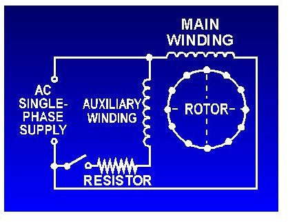
Capacitor Start Motors Diagram Explanation Of How A Capacitor
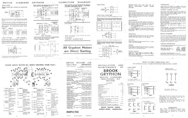
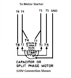
Brook Gryphon 1hp Motor Connection Diagram

Float Switch Installation Wiring Control Diagrams Apg
Single Phase Single Phase Motor Starter Wiring Diagram Buy
