Wiring Diagram For Modem

Rs 232 Connections That Work Connecting Devices Or Converters

53e Pk5001a Centurylink Modem Wiring Diagram Wiring Library

Xfinity Home Wiring Diagram Today Wiring Diagram Wiring Modem
Most modems are always on and dont have a power switch.

Wiring diagram for modem. If there is a power switch on the modem turn it on. A wiring diagram is a sort of schematic which uses abstract photographic icons to show all the affiliations of components in a system. This section will cover wiring with coaxial cable in your home and help you avoid common mistakes made when installing a catv location or cable modem in your home. It shows the elements of the circuit as streamlined forms and the power as well as signal connections in between the devices.
30102018 30102018 5 comments on att uverse arris bgw210 wiring diagram att u verse commonly called u verse is an att brand of triple play telecommunications. Figure 1 is the wiring scheme for the plug side of an rj 11 connector. The diagram is shown with the hook clip on the underside. This gallery contains network diagrams for wireless wired and hybrid home networks.
1 mistakes made when running coaxial cable. Network wiring instructions for rj11 and rj45 rj 11 telephone plug. But the overwhelming majority of homes had just one line. Most residential phone wiring in the us.
4 how to install the coaxial cable for your cable modem. Connect the modem power cord into an electrical outlet then connect the other end to the modem. A wiring diagram is a streamlined conventional pictorial representation of an electric circuit. Wiring diagrams are made up of 2 things.
These models are both composed of circuit boards providing service which are fed by fiber. Diagram 7 box to box vpn with modemrouters diagram 1 shows what occurs when using a modem that is only a single connection to the internet is possible. The typical rj 11 connector has six terminals. The following diagrams show what devices need to be used to obtain an internet connection form multiple devices.
The typical elements in a wiring diagram are ground power supply wire and link output gadgets switches resistors reasoning gateway lights etc. 2 how to install a connector on your cable. Symbols that represent the parts in the circuit and lines that represent the links between them. To check out a wiring diagram initially you have to know exactly what basic components are included in a wiring diagram and also which photographic symbols are used to represent them.
This four strand wire would support two separate lines. During the mid to late 1900s used four strand wire within the house with individual wires in insulation colored green red black and yellow. 3 cable tv splitters. Many home network layouts work fine but most are variations on a basic set of common designs.

812d8 2006 Caravan Headlight Wiring Diagram Wiring Resources
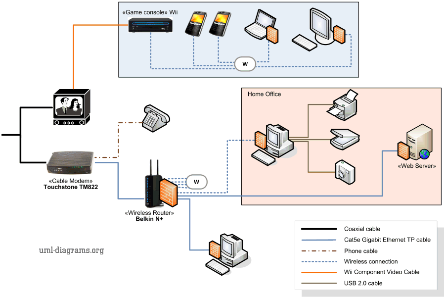
Example Of Home Networking Diagram Cable Modem Wireless Router
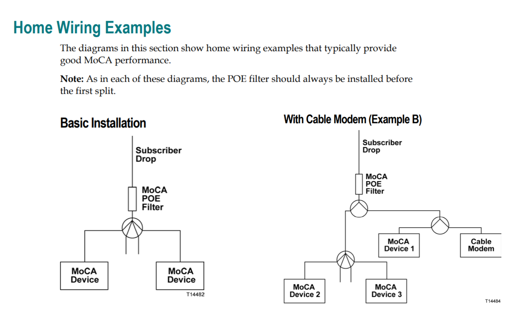
Proper Wiring Diagram For Tv Cable And Modem Wiring Diagram
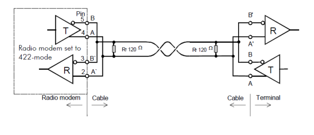
Faq Satel

Long Lines Diagrams
Internet Modem

X1 Modem Wiring Diagram

Gsm Gprs Gps Modem With Sim900 Sim908 Module Open Electronics

Null Modem Wikiwand
