Wiring Diagram For Sensor

Optical Level Sensor Wiring Diagram Madison Company

Accelerator Pedal Position Sensors Autosphere
Photoelectric Sensor
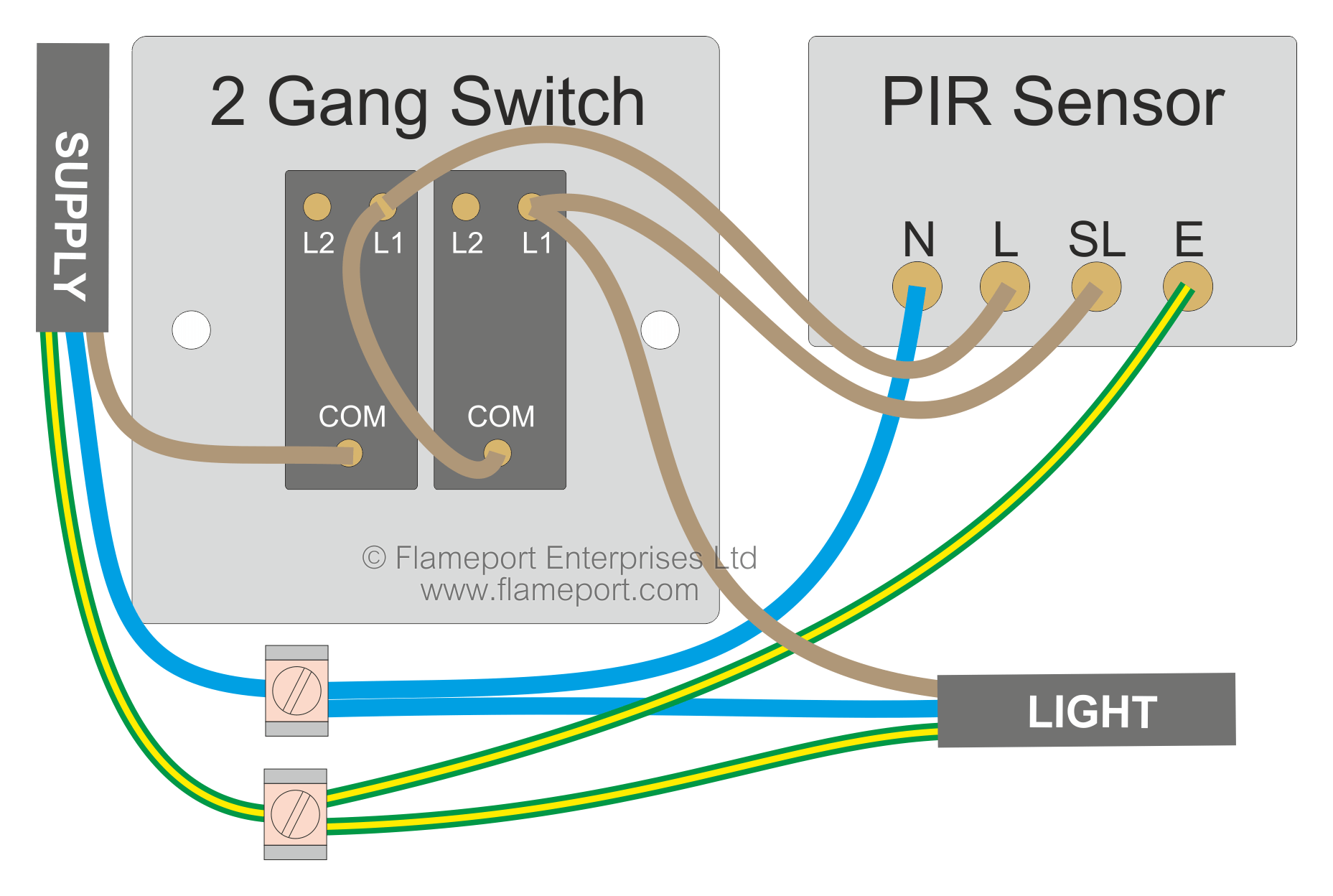
Connect sensors black wire to black wire coming from house.
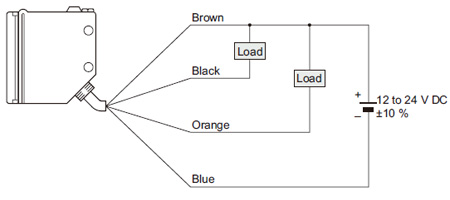
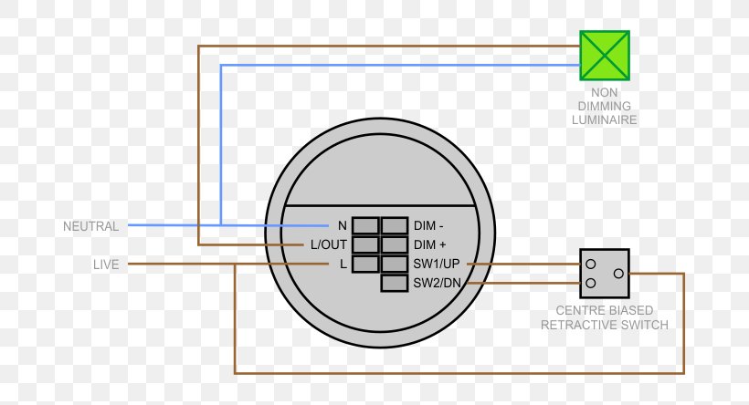
Wiring diagram for sensor. Refer to your particular model for any specific instructions or connections as various models may have different wiring methods. It reveals the elements of the circuit as streamlined shapes and also the power and also signal connections between the tools. The new sensor to be fitted is a titan tp140btp140w. Pnp switched positive.
Connect red sensor wire to lights black wire. 0 250psi pressure sensor diagram. The most common motion sensor will use a red insulated wire a black insulated wire and a white insulated wire. Oilfuel pressure flex fuel diagram.
0 1500psi pressure sensor diagram. How is the wiring connected for the motion sensor for a outdoor security light. A wiring diagram is a simplified conventional pictorial depiction of an electrical circuit. Variety of motion sensor light wiring diagram.
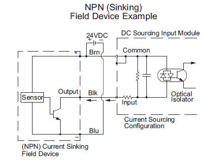
Npn switched negative switched refers to which side of the controlled load relay small indicator plc input is being switched electrically. Wiring diagrams wiring diagramsversion. Then after a few minutes where no movement has been detected the lights will then automatically shut themselves off. A motion sensor light switch is a great way of saving energy and helping out the planet by making your home greener and more energy efficient.
Collection of 2 wire proximity sensor wiring diagram. Heres a simple way remember how to wire up a 3 wire dc pnp or npn sensor. The 4 wire cable extrudes from the wall and is connected to the. Driveshaft speed sensor kit diagram.
Black wire is 120 volts so turn off switch or circuit breaker. Connect all 3 white wires from house from sensor and from light together. Universal tps wiring diagram. 0 150psi pressure sensor diagram.
0 100psi pressure sensor diagram. 60 2 trigger kit diagram. Typically three wires are attached to a motion sensor. 0 75psi pressure sensor diagram.
Here is my wiring diagram third photo and instructions. Im connecting a 4 wire cable to an outdoor sensor for a security light. 49 mb 4122016 ft450version. A wiring diagram is a streamlined standard photographic depiction of an electrical circuit.
The actual light is separate and already connected. It shows the components of the circuit as streamlined shapes and also the power as well as signal connections in between the devices. 052 mb ft550 6cil.

Robust Photoelectric Sensor Rx I O Circuit And Wiring Diagrams
Motion Sensor Wiring With Switched Override Feature

Oxygen Sensor Harness Plug In Location 1994 Chevy K1500 Pickup I

Dahuawiki
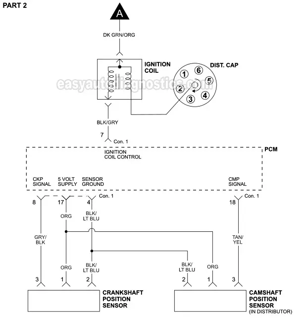
Ignition System Wiring Diagram 2001 2003 3 9l Dodge Dakota
Robust Photoelectric Sensor Rx I O Circuit And Wiring Diagrams

Ect Sensor Wiring Diagram Youtube

Automatic Room Light On Circuit Using Pir Motion Sensor Pir
Wiring Diagram Occupancy Sensor Electrical Wires Cable
