Wiring Diagram For Transmitter
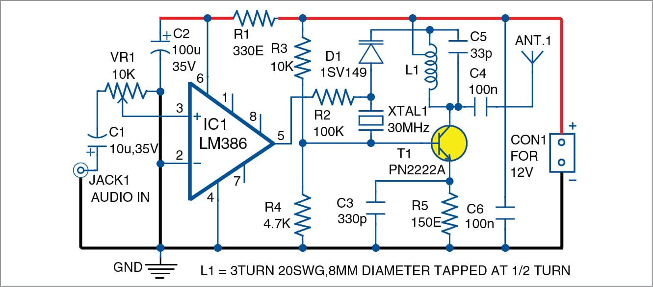
Simple Fm Transmitter For Broadcasting Full Electronics Project

Ultrasonic Level Transmitters
Rosemount Wiring Diagram Kobeds 7 Sandstrahlerei Laugwitz De
Wire tracer receiver.
![]()
Wiring diagram for transmitter. Transmitters are available with a wide variety of signal outputs. The 4 20ma analogue signal is by far the most commonly used in industrial applications. The base of the triangle is labeled r and refers to receiver. Etc can supply their internal circuitry.
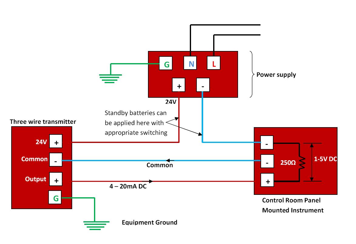
Some transmitters require more power than the signal loop 4 20 ma. We have covered 4 wire transmitter 3 wire transmitter and 2 wire transmitter. Several physical 4 20ma wiring options exist. Relay schematic circuit schematic diagram schematic diagrams starter relay studebaker wiring wiring connection wiring diagram wiring diagrams wiring harnes wiring schematic wiring system wiring work.
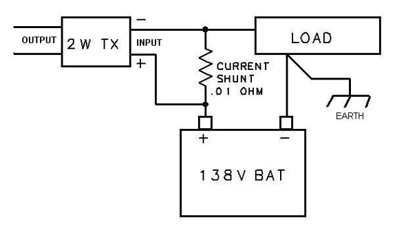
This guidance note aims to outline these options. Two wire transducer as shown in the above the power supply is 24 vdc output signal for the dc4 20 ma the load resistance is 250 w lowest negative line voltage of 24 v power supply it is the public line signal. Three wire transmitters. The right side of the triangle is labeled i and refers to the source of current or the power supply.
Introduction to the two wire transmitter and the 4 20ma current loop the left side is labeled t and refers to transmitter. The figure above shows the wiring diagram of the two wire transmitter. Hope this video is perfectly helpful for all those who.
Fm Transmitter Circuit Using 555
4 20ma Transmitter Wiring Types 2 Wire 3 Wire 4 Wire

18w Fm Transmitter Electronic Schematics Electronics Circuit

Ir Transmitter And Receiver Circuit Diagram
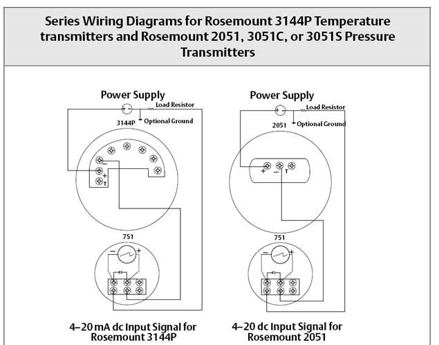
Rosemount Wiring Diagram Kobeds 7 Sandstrahlerei Laugwitz De
Easy Fm Tracking Transmitter Electronic Schematic Diagram
Wilkerson Instrument Company Inc Blog Dc Input Isolated 2

Kd 4658 Fm Transmitter Circuit Diagram Bf494 Electronics Circuits

Rosemount Wiring Diagram Kobeds 7 Sandstrahlerei Laugwitz De
