Wiring Plc Ladder Diagram

Interlocking Functions Of Plc Program Of Ladder Diagram Plc One

Automation Manufacturing System With Plc

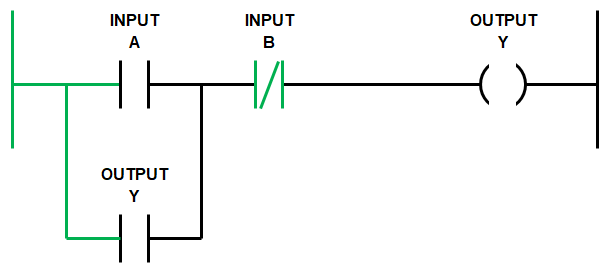
Ladder Logic 202 Outputs Automationprimer
When including a plc in the ladder diagram still remains.
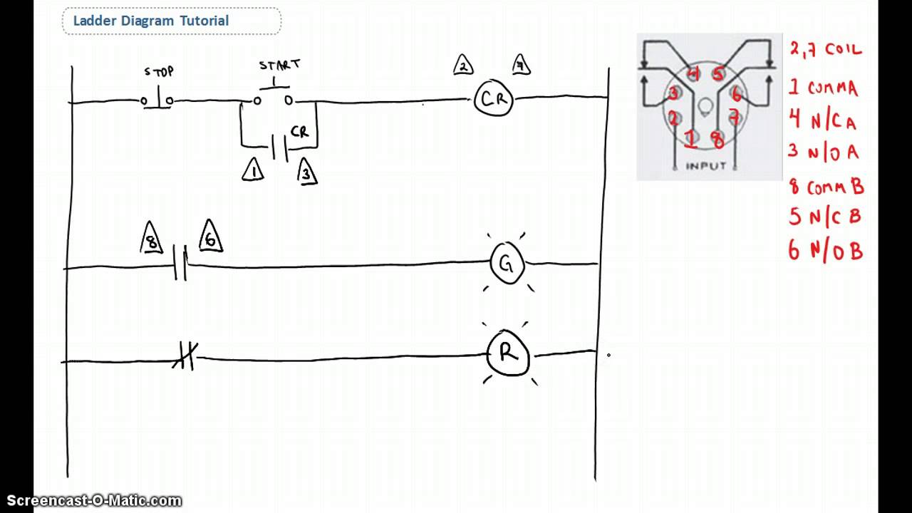
Wiring plc ladder diagram. But it does tend to become more complex. Lets start converting our simple wiring diagram to the plc program in a step by step format. Just like on the diagram we start with the stop push button. This is a continuation of the previous article introduction to plc ladder programming in plc programming seriesplease go through an introduction to ladder programming before reading this post.
Gambar layar cx programmer disebut tangga karena mereka menyerupai tangga dengan dua rel vertikal kanan kiri power supply dan banyak anak tangga garis horizontal yang mewakili rangkaian kontrol. Im using the siemens tia portal as the plc programming software. As an introduction to ladder diagrams consider the simple wiring diagram for an electrical circuit in figure 1athe diagram shows the circuit for switching on or off an electric motor. A wiring diagram is an electrical print that shows connections of all components in a piece of equipmenta schematic diagram is a type of drawing that illustrates the electrical connections and functions of specific circuit arrangements with graphic symbolsa ladder diagram is a diagram that explains the logic of the electrical circuit or system using standard nema or iec symbols.
Introduction to plc ladder diagrams. Pemrograman ladder diagram dapat dilakukan dengan software plc cx programmer yaitu software pemrograman plc yang dimiliki oleh plc dengan brand omron. Ladder diagram basics 3a nema contactor. This figure shows the e stop wired to cutoff power to all of the devices.
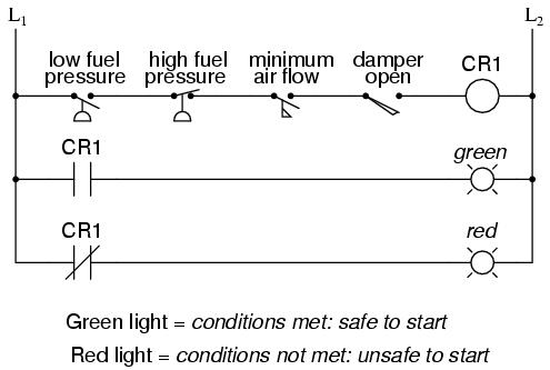
Figure 5 below shows a schematic diagram for a plc based motor control system similar to the previous motor control example. These look like a normally closed nc contact. The most common language used to program plcs is ladder diagram ld also known as relay ladder logic rll. Programming allen bradley slc 500 controllogix plc intro duration.
In this post we will discuss about what is a ladder diagram and how to draw a ladder diagram. Wye delta control circuit wiring tutorial tagalog basic motor. Ladder diagram ld programming. It will be represented with an examine off bit.
Lessons In Electric Circuits Volume Iv Digital Chapter 6

Logic Gates In Plc Ladder Logic Instrumentation Tools

Lessons In Electric Circuits Volume Iv Digital Chapter 6
1592315530000000

Mitsubishi Fx Plc Crosswalk Programming Ladder Diagram Plc One

Gc 4618 Examples Of Plc Ladder Logic Diagrams
Ladder Logic Programming Examples Ladder Logic World
Ladder Diagram Basics 1 Youtube

Plc Wiring Diagrams And Ladder Logic Programs
