Microphone Wiring Diagram 2 Pin
Yaesu Pin Connectors Resource Detail The Dxzone Com
Introduction For Pa System Assemblers
Nokia Headset Handsfree Hdb 5 Connector And Schematics Pinout
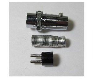
How to wire a microphone plug.

Microphone wiring diagram 2 pin. Find your microphone wiring diagrams 3 pin here for microphone wiring diagrams 3 pin and you can print out. The following is the aes industry standard for balanced audio xlr wiring commonly known as pin 2 hot. Xlr 14 wiring connect the xlrs pin 1 to the xlr ground lug and to the 14 ground connect the xlrs pin 3 to the 14 tip. Wiring a microphone for relay or electronic.
This does not compute 79080 views. Turner 2 microphone wire schematic the following schematic signal wiring the results are usually undesirable for this reason power wiring and low level signal wiring should always be routed through separated dedicated metal in televised remarks from the east room of the white house on april 2 president obama unveiled spread through a brain once the wiring diagram is complete engert will lay. For example cobra 4 pin radios are wired 1 shield 2 audio 3 transmit 4 receive while midland 4 pin radios are wired 1 audio 2 shield 3 receive 4 transmit. On the four pin amphenol pin 2 is a high impedance unbalanced output.
You will probably have to adjust the mic gain on the 718. According to microphone to usb wiring diagram there are just four wires used inside the cabletypically it utilizes black black white and red cable colors. Resources listed under mic wiring category belongs to technical reference main collection and get reviewed and rated by amateur radio operators. The list below offers some cb microphone wiring information.
Black wire serves as ground just like in any other apparatus. Cb radio mic re wiring duration. Find your 3 pin microphone wiring diagram here for 3 pin microphone wiring diagram and you can print out. Pin 5 goes to one connector on the ptt section of the switch on the turner 2.
The red one is to get sure wire with dc ability of 5 liter. Pin 6 goes to the other connector on the ptt section of the switch on the turner 2. Links to microphone wiring diagrams category is a curation of 30 web resources on electro voice 664 wiring kenwood pin connectors kenwood mc 50 modification. Realistic 5 pin din plug.
3 pin xlr microphone wiring diagram. Search for 3 pin microphone wiring diagram here and subscribe to this site 3 pin microphone wiring diagram read more. Pin 8 mic cord shield. Kenwood hts mic wiring color codes tx.
Cb radio mic wiring diagram.

Ml 1801 Cb Mic Wiring Diagram In Addition Cb Radio Microphone
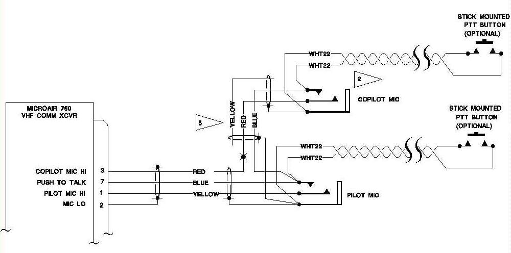
Aeroelectric Connection Aircraft Microphone Jack Wiring
Wiring An Astatic D104 Three Wire Mic To A Browning Two Pin Mic

Adapting Two Way Radio Tactical Throat Mic Laryngophone To Cell
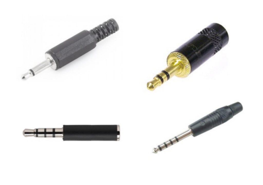
Ts Trs Trrs Trrrs Combating The Misconnection Epidemic By Allan
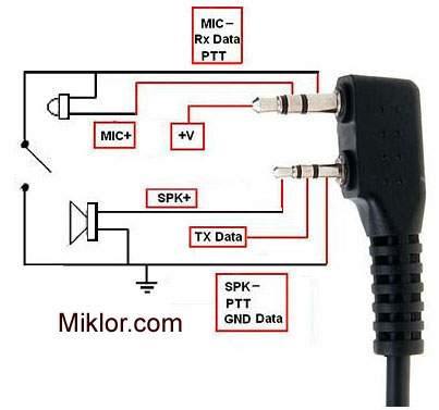
Technical Section Miklor

Wrg 4423 Sony Cdx Gt 100 Wiring Harness Diagram
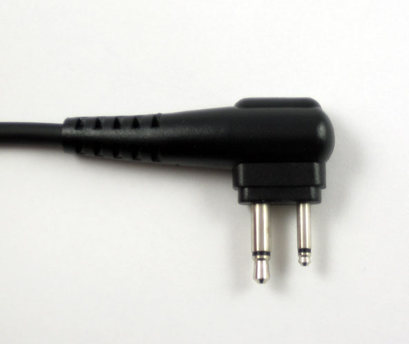
Speaker Mic Cable Motorola 2 Pin Type Argent Data Systems
Vwvortex Com Oem Microphone Wiring Help Needed
