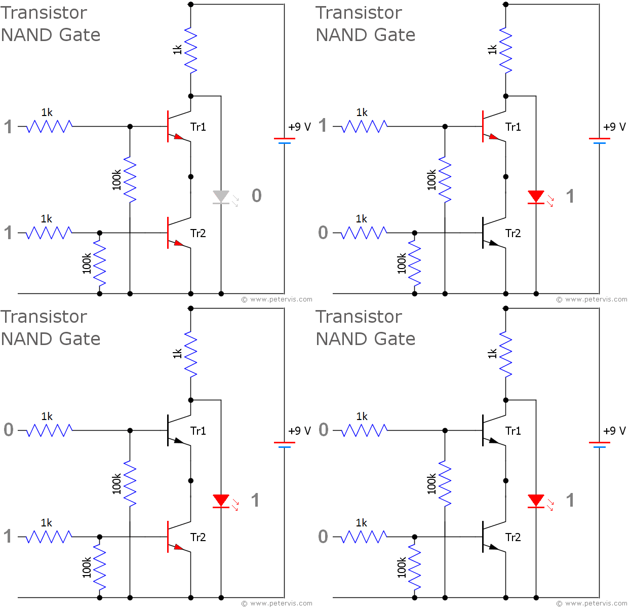
Nand Gate Logic Diagram
Logic diagram truth table nor gate.

Nand gate logic diagram. The boolean expression for a logic nand gate is denoted by a single dot or full stop symbol. The logic or boolean expression given for a logic nand gate is that for logical addition which is the opposite to the and gate and which it performs on the complements of the inputs. With a line or overline over the expression to signify the not or logical negation of the nand gate. Nand gate is operated as an and gate and followed by the inverter.
Since a nand gate is equivalent to an and gate followed by a not gate joining the inputs of a nand gate leaves only the not gate. We know that a half adder circuit has one ex or gate and one and gate. A nand gate is a universal gate meaning that any other gate can be represented as a combination of nand gates. So lets see how basic logic is implemented using nands only.
A nand gate is made using transistors and junction diodes. As we know that nand and nor are called universal gates as any logic system can be implemented using these two the half adder circuit can also be implemented using them. A can be implemented by the following nand gate. If any input is low 0 a high 1 output results.
A not gate is made by joining the inputs of a nand gate together. A not or operation is known as nor operation. It has n input n 2 and one output. Given function f x yz is a boolean function when it receives a combination of input values it will evaluate a single output value based on the expression or boolean function.
A not and operation is known as nand operation. For all other cases the output will be high. Logic diagram truth table nand gate. Nand gate is a digital logic gate designed for arithmetic and logical operations every electronic student must have studied this gate is hisher career.
Thus its output is complement to that of an and gatea low 0 output results only if all the inputs to the gate are high 1. Nand gate logic symbol boolean expression truth table gate logic flow schematic diagram nand gate construction and working mechanism nand gate from other gates multiple input nand gate ttl and cmos logic nand gate ics pinout for 7400 ttl nor gate ic nand gate applications. It has n input n 2 and one output. Logic gate truth table for nand gate.
In digital electronics a nand gate not and is a logic gate which produces an output which is false only if all its inputs are true. If you know how basic logic not and or is implemented using nand you can implement any logic no matter how complex. Xor or ex or gate is a special type of gate. Logic diagram truth table xor gate.
What is logic nand gate. So a a. Show the result in truth table and draw a logic diagram using only nand gate.