O2 Sensor 4 Wire Oxygen Sensor Wiring Diagram
Https Encrypted Tbn0 Gstatic Com Images Q Tbn 3aand9gcrapc6pb3 Yj4fjdm9mgj2glof7szgpgwhvl 4t5fyibos0n9sj Usqp Cau

Ford Mustang Oxygen Sensor Diagram Diagram Base Website Sensor
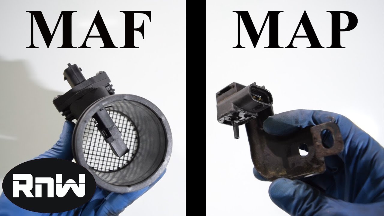
How To Test A Maf Or Map Sensor With A Multimeter Plus An
Find your 4 wire oxygen sensor wiring diagram here for 4 wire oxygen sensor wiring diagram and you can print out.
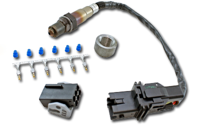
O2 sensor 4 wire oxygen sensor wiring diagram. The four wire universal oxygen sensor must be changed approximately every 60000 miles and requires a specific wiring process. As the o2 heater is resistor based polarity is not a concern here. How to test a mass air flow maf sensor without a wiring diagram. Plus oxygen sensor operation and replacement.
Note down which two wires correspond to the heater circuit and proceed to test 2. I was going to use a 4 wire sensor but to run the wiring was too much trouble so i used a universal 3 wire o2 as it was easier to install. Explains the o2 sensor heater wiring test using cost effective procedures. Determine sensor signal polarity.
It reveals the components of the circuit as streamlined forms and also the power as well as signal links between the tools. The o2 or oxygen sensor is in charge of measuring the content of the exhaust. Right here are several of the top drawings we obtain from different sources we hope these photos will certainly work to you and ideally really pertinent to what you desire concerning the oxygen sensor wiring color codes is. Our people also have some more graphics associated to oxygen sensor wiring color codes please see the image gallery below click one.
Btw 87 did not have 4 wire sensors starting in 88 did toyota use 4 wire sensors. What i do remember is the following. This is the remarkable ntk oxygen sensor wire diagram pictures schematic of a graphic i get coming from the oxygen sensor wiring color codes package. Search for 4 wire oxygen sensor wiring diagram here and subscribe to this site 4 wire oxygen sensor wiring diagram read more.
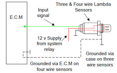
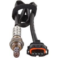
Learn about the o2 sensor electrical connection and how it relates to the ecm and signal output. This sensor measures the amount of unburned oxygen that is present in the oxygen as it exits the vehicle which is indicative of the fuel mixture. Variety of 4 wire oxygen sensor wiring diagram. The blue is signal the original o2 wire.
Oxygen sensor wiring diagram wiring diagram collection koreasee size. You can save this pics file to your individual laptop. The o2 sensor signal gives an indication of oxygen content sensed by the probe by sending an induced voltage that corresponds to the level of oxygen detected. If not the structure will not work as it ought to be.
4 wire oxygen sensor wiring diagram 4 wire 02 sensor wiring diagram 4 wire lambda sensor wiring diagram 4 wire o2 sensor wiring diagram honda every electric arrangement is made up of various unique parts. Please right click on the image and save the graphic.

Oxygen Sensor Locations

1x New Bosch Lsu 4 9 5 Wire Wide Band Oxygen Sensor 0258017025

Mechanical Pg B

Magnum O2 Sensor Simulator To 3 Or 5 Volt 4 Wire Wideband Sensors
Lambda Sensor Wire Colour Mitsubishi Lancer Register Forum

Ntk Technical Tips From Component Distributors
Index Of Sensors
O2 Sensor Oxygen Sensors For Your Car Truck Or Suv
Extreme Psi Your 1 Source For In Stock Performance Parts
