Outlet Switch Light Wiring Diagram

30v30r 3 Way Switch Wiring 6 Way Switch Light Wiring Diagram Hd
Single Pole Light Switch To Outlet Wiring Diagram
Wiring Diagrams To Add A New Light Fixture Do It Yourself Help Com
Wiring a gfci combo switchoutlet with protected light outlet receptacle.

Outlet switch light wiring diagram. It means all the connected loads to the load terminals of gfci are protected. This electrical wiring question came from. This wiring diagram illustrates adding wiring for a light switch to control an existing wall outlet. This page contains wiring diagrams for household light switches and includes.
A switch loop single pole switches light dimmer and a few choices for wiring a outlet switch combo device. Fishing in a wire from the receptacle to the light fixture is fairly easy so this is how you would wire the switchreceptacle combo device in this situation. Is it possible to wire a switch for a light and at the same time connect an outlet to the switch that will not power off and on with the switch. Wiring an outlet to a switch loop.
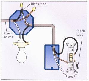
This wiring diagram depicts the electrical power from the circuit breaker panel entering the switched electrical receptacle outlet box where a two wire cable goes to the switch and another two wire cable feeds power to another outlet that is live at all times. Scenario 2 a typical example of this situation is if you had the same scenario as above but with a 3 wire circuit such as in a kitchen split receptacle and wanting to add some under counter lighting for example. The photo above depicts the wiring diagram of a ceiling light and light switch with the power from the circuit breaker panel entering the ceiling electrical box. From the ceiling a three conductor cable with a grounding conductor is used to send power to a light switch.
In this special case wiring diagram both light and ordinary outlet is connected to the load terminals of gfci. The source is at the outlet and a switch loop is added to a new switch. Mike a handyman from fort dodge iowa. In this gfci outlet wiring and installation diagram the combo switch outlet spst single way switch and ordinary outlet is connected to the load side of gfci.
The light onoff operation can be controlled through the gfci switch while the ordinary outlet is directly connected to the gfci load terminals. Wiring a switch with an outlet.
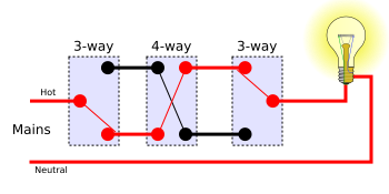
Multiway Switching Wikipedia

Light Switch Wiring Load Simple Gfci Outlet With Switch Wiring

Electrical Wiring Household Skills Power Grid All Electrical

How To Wire Combination Switch Outlet
Wiring A 2 Way Switch

Light Switch Wikipedia

Light Switch Wiring Electrical 101

Wire Light Switch Diagram Wiring Diagram E7

Related Posts Outlet Controlled By Switch And Light Not Working
