Paragon Timer Wiring Diagram

Paragon Timers And Manuals
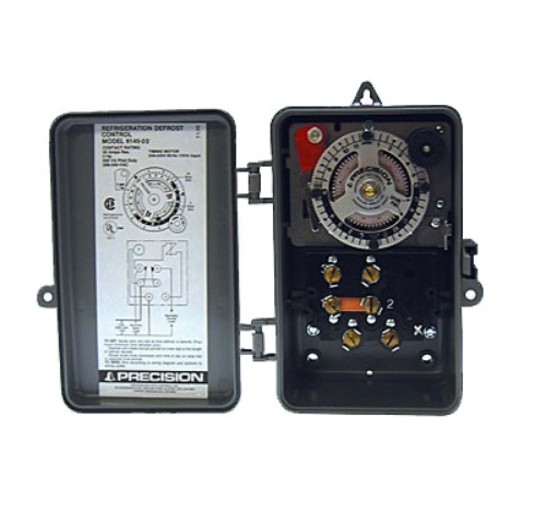
Precision Multiple Controls Official Website Your Source For

Solved Lost Instruction Manual How Do I Progam My Paragon
Defrost clock wiring diagram and freezer timer to paragon 8145 20.

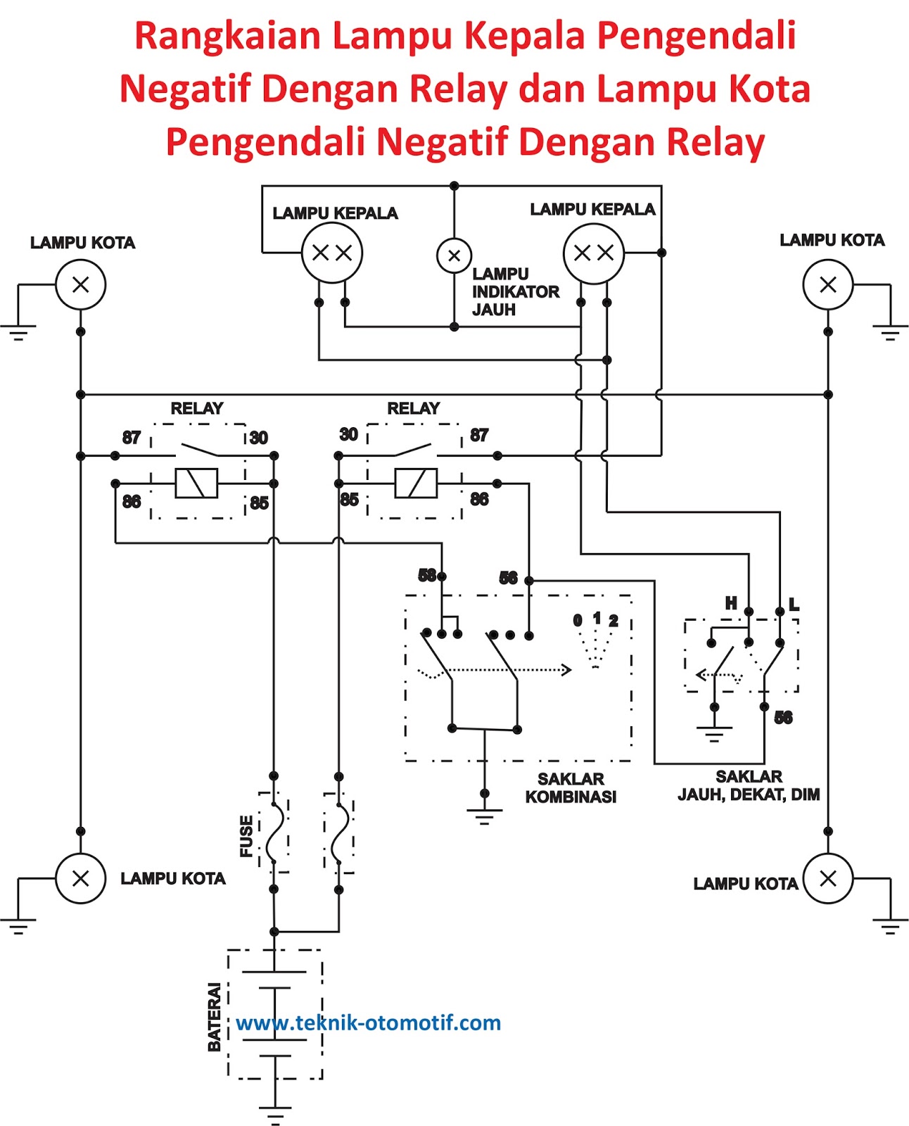
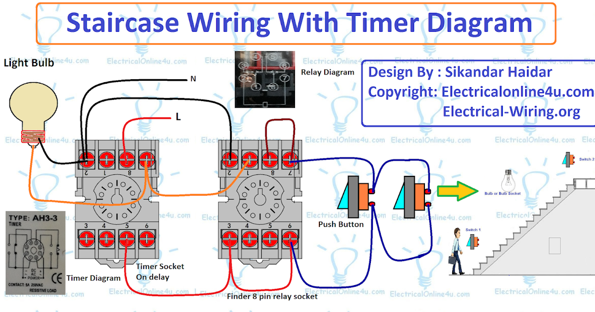
Paragon timer wiring diagram. It shows the components of the circuit as simplified forms as well as the power and signal connections between the devices. This timer controls two. Collection of paragon defrost timer 8145 20 wiring diagram. Installing instruction for installing an intermatic t101 or t103.
Defrost timer wiring diagram bestharleylinksfo. We show where to connect the neutral wire. Click on the image to enlarge and then save it to your computer by right clicking on the image. Collection of paragon 8141 00 wiring diagram.
It reveals the elements of the circuit as simplified forms and also the power and also signal connections between the tools. Assortment of paragon 8145 00 wiring diagram. Paragon 8145 00 wiring diagram timer wiring diagrams wiring harness wiring diagram wiring wire rh linxglobal co. Where the black hot wire goes.
Assortment of paragon 8145 00 wiring diagram. Im a student in school and im tring to find installation operating instructions for the paragon defrost controlparagon 00 wiring diagram timer 20 somurich 1 on defrost image info file name. Paragon defrost timer wiring diagram paragon defrost timer wiring regarding 20 wiring diagram image size x px and to view image details please click the image. A wiring diagram is a streamlined traditional pictorial depiction of an electric circuit.
It reveals the parts of the circuit as simplified forms and the power and signal connections in between the gadgets. A wiring diagram is a streamlined traditional pictorial depiction of an electric circuit. Paragon timer wiring diagram 09122018 09122018 4 comments on paragon timer wiring diagram the paragon series auto voltage defrost timer is designed competitive voltage specific mechanical defrost timers eliminating wiring diagrams. Collection of paragon defrost timer 8145 20 wiring diagram.
We show how to test the timer. A wiring diagram is a simplified traditional photographic depiction of an electrical circuit. A wiring diagram is a simplified traditional photographic depiction of an electric circuit.
Commercial Defrost Timer Wiring Diagram

To Paragon Timer Timers Wiring Diagrams Diagram Base Website

Cb3d9 Precision Defrost Timer Wiring Diagram Wiring Library
Aes E Library Complete Journal Volume 49 Issue 7 8
To Paragon Timer Timers Wiring Diagrams Diagram Base Website

Whirlpool Defrost Timer Wiring Diagram General Wiring Diagram

Wrg 7045 40 Rv Inverter Wiring Diagram Free Picture
Grlin Timer Wiring Diagram Diagram Base Website Wiring Diagram

Paragon Timers And Manuals
