Parallel Circuit Series Circuit Diagram

Series V Parallel The Worm That Turned Revitalising Your

Simple Electrical Circuits Mechanical Aptitude Tests

Parallel Circuits Series And Parallel Circuits Siyavula
Here we have a series circuit with a battery an led and a resistor.
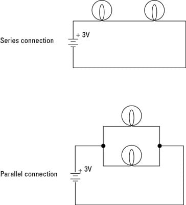
Parallel circuit series circuit diagram. Web editor embed description netlist beta. Tutorial for the sequence of combining resistors. Components of an electrical circuit or electronic circuit can be connected in series parallel or series parallel. And unlike a series circuit the lamps stay.
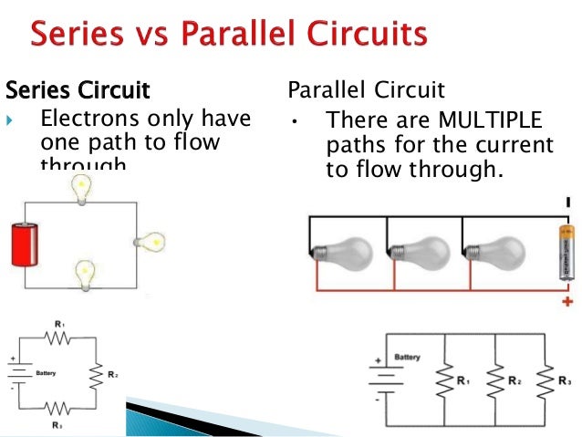
Components connected in series are connected along a single conductive path so the same current flows through all of the components but voltage is dropped lost across each of the resistances. Doc schuster 1390782 views. This circuit demonstrates some of the components that can be simulated. Sneak a peek at figure 1.
Microcontroller setup by matthias mayer. A simulation is used to visualize electron flow through both circuit types. Parallel and series resistor circuit analysis worked example using ohms law reduction doc physics duration. The two simplest of these are called series and parallel and occur frequently.
Parallel and series by emma mitchell. Parallel and series by emma mitchell. Series and parallel circuits. This is a new feature we are working to.
Intro music atribution title. Sound trigger by matthias mayer. For our comparison of series vs parallel circuits lets start by talking about the simplest circuit of all the series circuit. Project 3 by miranda c.
A series capacitor circuit is an electronic circuit in which all the capacitors are connected one after another in the same path so that the same charge or current flows to each capacitor. First an example of a series circuit. There are two basic ways in which to connect more than two circuit components. Here we have three resistors labeled r 1 r 2 and r 3 connected in a long chain from one terminal of the battery to the other.
The main difference between series and parallel circuits is that in series circuits all components are connected in series so that they all share the same current whereas in parallel circuits components are connected in parallel so that they all have the same potential. Main difference series vs. Series vs parallel circuits series vs parallel. This circuit was created by a member of the community and has no affiliation to the circuit diagram project.

How To Use A Multimeter
Electronics Projects How To Build Series And Parallel Circuits
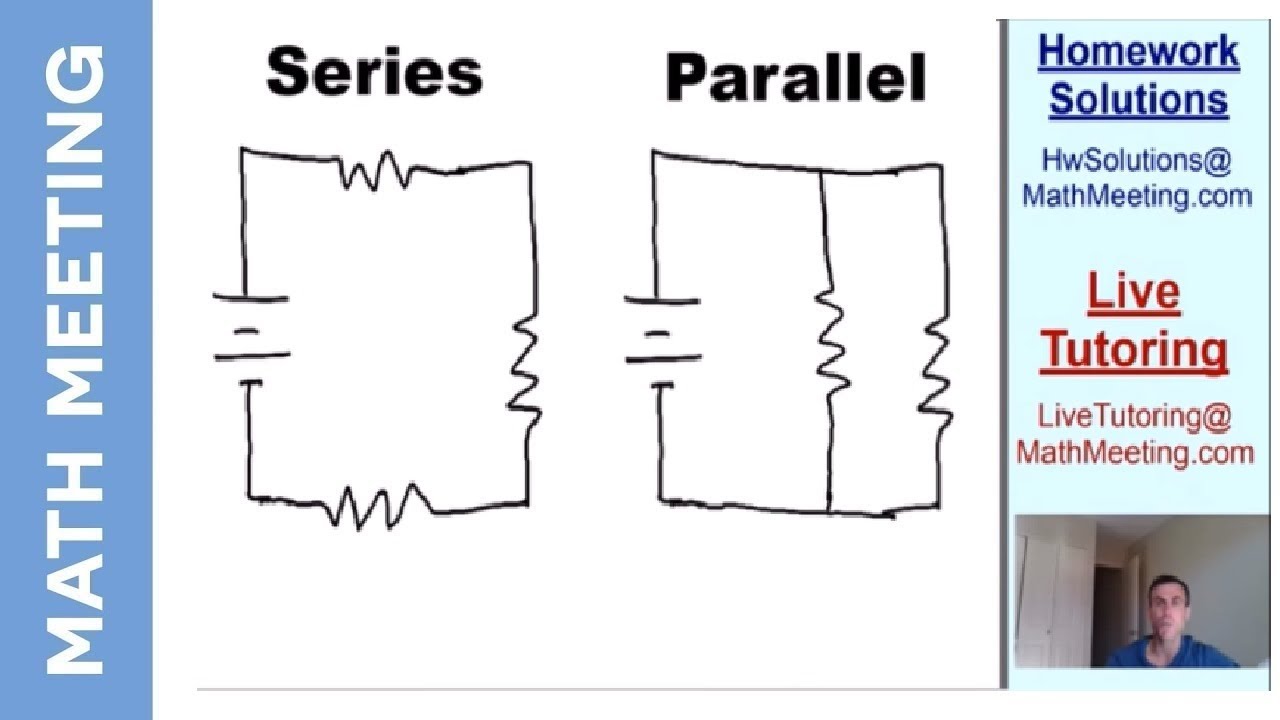
Introduction To Circuits Series Vs Parallel Circuits Youtube

Parallel Circuits Series And Parallel Circuits Siyavula
Series And Parallel Circuits Learn Sparkfun Com
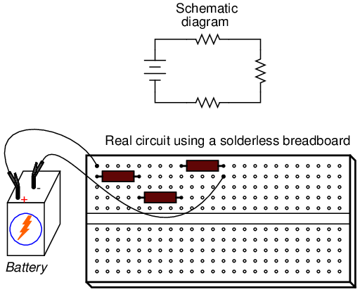
Lessons In Electric Circuits Volume I Dc Chapter 5
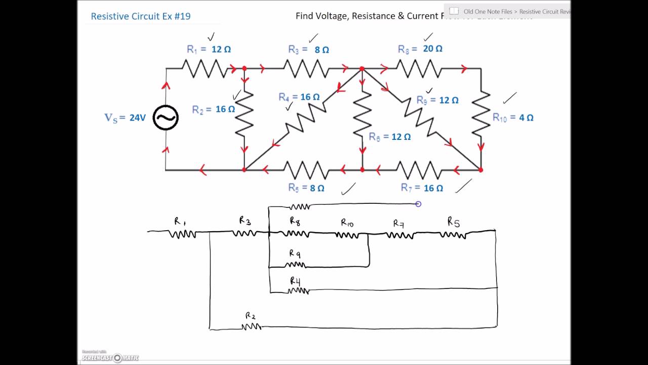
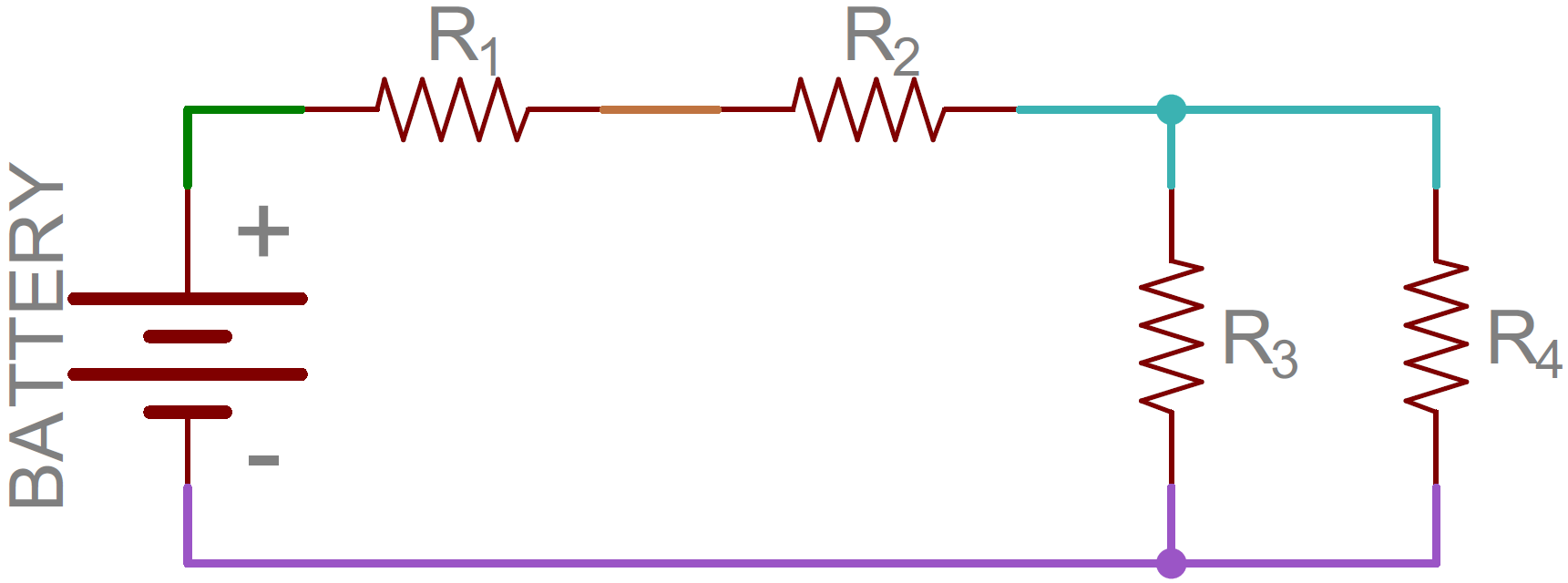
Series Parallel Combination Circuit 19 Youtube
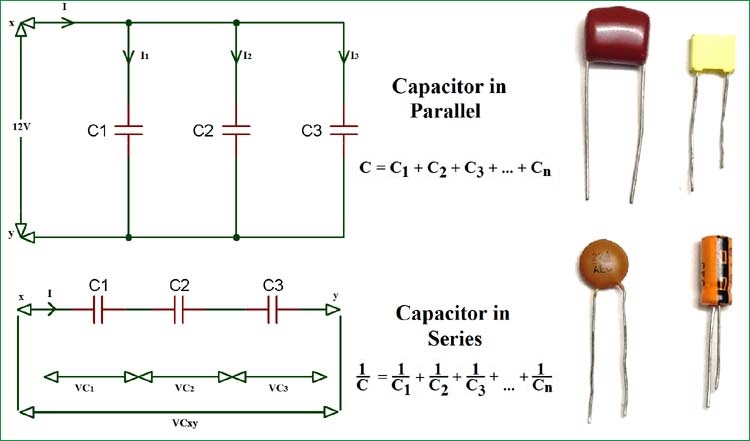
Capacitor Circuits Capacitor In Series Parallel Ac Circuits

Series Rlc Circuit And Rlc Series Circuit Analysis
