Patch Cable Wiring Diagram
Repeat the procedure on the other end of the cable using the same wiring diagram.

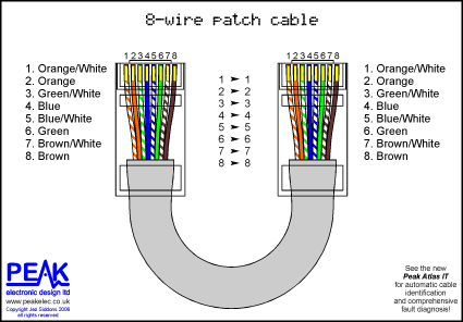
Patch cable wiring diagram. When you are doing the straight through wiring the cable pinout on the two ends of the cat5e cable should be the same. There are two basic ethernet cable pin outs. For this we recommend our lantest pro cable tester. Notes regarding making category 6 patch cable.
If you require a cable to connect two ethernet devices directly together without a hub or when you connect two hubs together you will need to use a crossover cable instead. Both the t 568a and the t 568b standard straight through cables are used most often as patch cords for your ethernet connections. Modular connector plug and jack pin out ethernet cable pin outs. Virtually all pre assembled patch cables are wired to the b standard.
A straight through ethernet cable which is used to connect to a hub or switch and a crossover ethernet cable used to operate in a peer to peer fashion without a hubswitch. If you wish to make a crossover cable than use the other diagram in this case 568 a 14. Remember the rj45 wiring order. For patch cables 568 b wiring is by far the most common wiring method.
The following picture shows the wiring diagram of the two standards. Click to check the right one for you or print as reference. There is no difference in connectivity between 568b and 568a cables. Httpgoogllwifis monoprice cat6 patch cable build tutorial.
Rj45 pinout diagram shows wiring for standard t568b t568a and crossover cable. However for the crossover wiring method the rj45 pinouts on each end of the cat5e are different. Test the cable using a high quality four pair tester. Click to find view print and more.