Piping And Instrumentation Diagram

Pdf Automatic Information Extraction From Piping And
Piping And Instrumentation Diagram Png Images Pngegg

Ro 2268 Piping Diagram Pictures Download Diagram
A piping and instrumentation diagram pid is a detailed diagram in the process industry which shows the piping and process equipment together with the instrumentation and control devices.
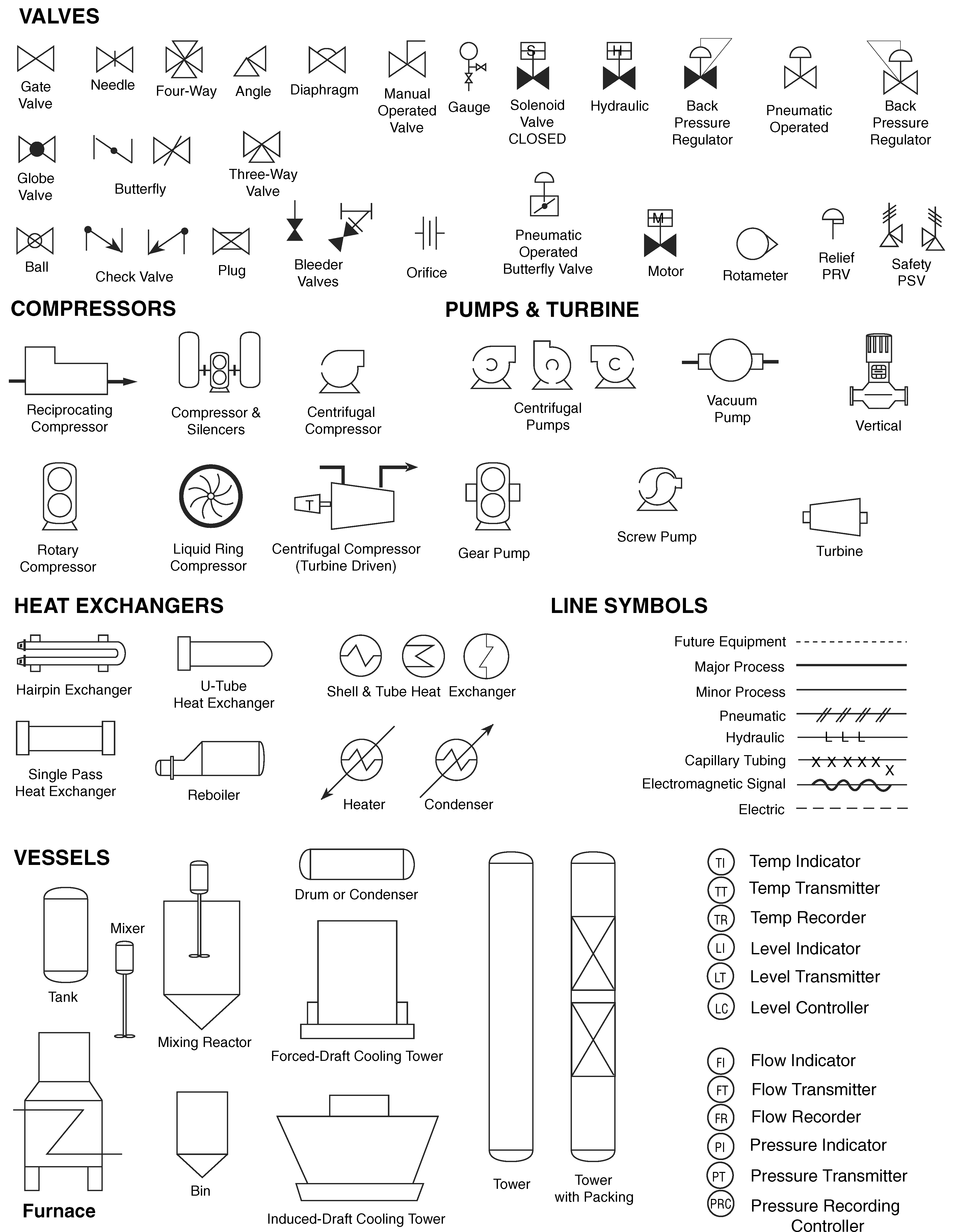
Piping and instrumentation diagram. Superordinate to the pid is the process flow diagram pfd which indicates the more general flow of plant processes and the relationship between major equipment of a plant facility. It helps in equipment design and piping design and also serves to estimate the capital cost. Hazard and operability hazop study is performed during the design stage with the help of pi diagram. Figure 7 shows commonly used symbols for indicating the medium carried by the piping and for differentiating between piping instrumentation signals and electrical wires.
Pid diagram online drawing tool. The pids are used to operate process systems. Piping and instrumentation diagram pid is a schematic illustration of a process flow between all process units or equipments in a plant. This video explain full details about piping and instrumentation diagrampid drawing process details step by step thanks for cc to.
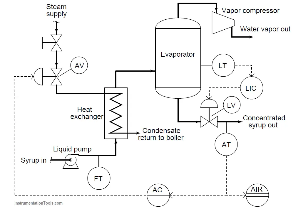
Questions on piping and instrumentation diagrams in this post we shared the 12 questions on piping and instrumentation diagrams related to the steam heat exchanger level analytical control loop. The piping and instrumentation diagram also called pid illustrates the interactions of the piping equipment and instrumentation of a physical process flowpids are often used in the process industry to show the process flow other installed equipment and instrumentation. Piping and instrumentation diagram is the basis for developing the control systems in the chemical process. The pid is one of the most important document produced by the process department.
Pids shows all piping including physical sequences of branches reducers valves equipment instrumentation and control interlocks. The symbology for the identification of the measurement and control instrumentation on the flow and process diagrams and on the pid piping instrument diagram commonly called pi piping instrumentation is generally compliant with the standard isa instrumentation society of automation identified as s5 that is composed of identification codes and graphic symbols.
Questions On Piping And Instrumentation Diagrams

Fire Water Pump Station Design Piping Instrumentation Diagram
Piping And Instrumentation Diagram Of The Setup Download

Pressure Regulator Relief Valve Control Valves Piping And
The Festo Mpp Piping And Instrumentation Diagram P Id

Piping Instrumentation Diagrams Guide Lucidchart

7 Best Hindi Images Piping And Instrumentation Diagram
Https Encrypted Tbn0 Gstatic Com Images Q Tbn 3aand9gcqlpr8jo9gzbpmdvnnmtle6vo Kpbrxnucx2hyzw16twygvgiai Usqp Cau

Piping And Instrumentation Diagram Png Images Pngegg
