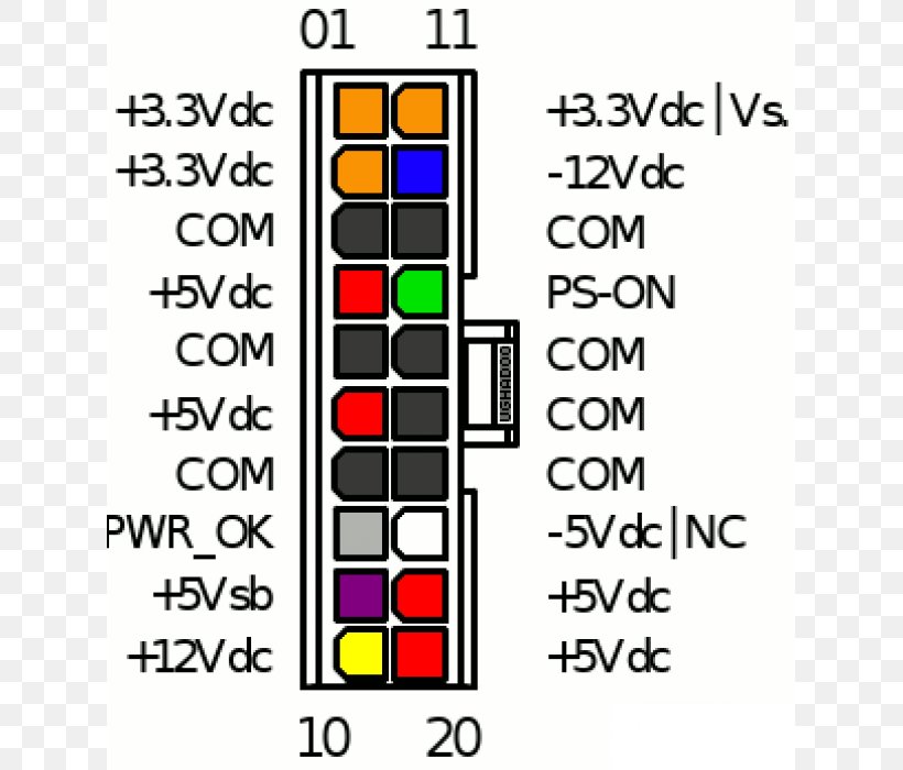
Power Converter Wiring Diagram
Wfco 8955 wiring diagram wfco 8955 converter wiring diagram wfco 8955 wiring diagram every electric arrangement is composed of various distinct components.

Power converter wiring diagram. The 91009200 series converters should have a minimum of 5 of clearance or sufficient ventilation to ensure adequate airflow into and out of the compartment containing the converter. Rv power converter wiring diagram on 2006fleetwooddiagramgif within rv power converter wiring diagram image size 1024 x 599 px and to view image details please click the image. Otherwise the structure will not function as it should be. If the 110 volt breaker feeding the convrter trips unplug the shure line and disconnect the 110 volt wires inside the converter reset the breaker and plug shore line in again.
Each component should be placed and linked to different parts in particular way. A power converter typically has four terminals. Rv power converter wiring diagram rv power converter wiring diagram rv power inverter wiring diagram every electrical structure consists of various distinct parts. Magnetek power converter 6345 wiring diagram.
Collection of magnetek power converter wiring diagram. Here is a picture gallery about rv power converter wiring diagram complete with the description of the image please find the image you need. Connect the coach battery negative terminal to a white wire. Each component should be placed and connected with other parts in specific manner.
Jan 31 bob yep my convertercharger. Connect the shore. Otherwise the arrangement will not function as it ought to be. The four terminals will be printed or embossed with their function and the usual lay out of color coded wires to terminals is to connect the coach battery feed terminal to a red or black wire.
Progressive dynamics 91009200 series inteli power converters can be mounted in any position without adversely affecting operation. Phillips power converter test procedure part i do not remove the converter from the recreational vehicle testing converter 1. A wiring diagram is a simplified standard pictorial representation of an electric circuit. It reveals the parts of the circuit as simplified shapes and the power and also signal links in between the devices.
Consult the instructions provided with the device and wire it accordingly.