Precision Full Wave Rectifier Circuit Diagram
Https Encrypted Tbn0 Gstatic Com Images Q Tbn 3aand9gcruscgky4ioon4b720llenrwjhxniipi4u0agn9zhqv4bzqwys3 Usqp Cau

Precision Rectifiers Explained
Op Amps Precision Rectifiers
Precision full wave rectifier.
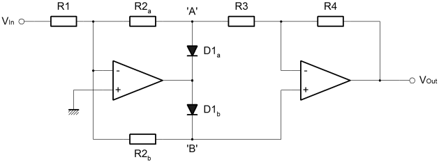
Precision full wave rectifier circuit diagram. A precision peak detector when the peak detector required to hold the value of the peak for a long time the capacitor should be buffered. From the point p1 to point p2 is the basic precision rectifier circuit and the diode is so configured that we get a negative voltage at the output. Remains very accurately full wave rectified as displayed with a 1khz input signal in figure 7. The circuit shown above performs full wave rectification on the input signal as shown.
Precision full wave rectifier using op amp. The rest of the circuit is similar to the half wave rectifier. The first section of negative ips operates as a closed loop inverter a 1 and the second section is just a buffer for the positive op. To make a full wave precision rectifier circuit i have just added a summing amplifier to the output of the previously mentioned half wave rectifier circuit.
The schematic diagram below describe a precise full wave rectifier circuit. If you wish the final output to be positive instead of negative simply reverse the two diodes in the half wave rectifier section. During the positive cycle of the input the signal is directly fed through the feedback network to the output give the transfer function of voutr3r1r2r3. The circuit needs only a single supply make it suitable for battery operated devices.
The precision rectifier using lt1078 circuit is shown above. The precision full wave rectifier circuits accept an ac signal at the input inverts either the negative or the positive half and delivers both the inverted and noninverted halves at the output as shown in the fig. Ti precision designs circuit description ti precision designs are analog solutions created by. 4 precision full wave rectifier dual supply tidu030 december 2013 revised december 2013.
The diagram below shows an inverting type of precision fwr with positive output. When the ip signal is ve then the output of first op amp remains saturated near gnd and the diode turn into high impedance letting the signal to flow straight to the buffer stage non inverted. The full wave rectifier depends on the fact that both the half wave rectifier and the summing amplifier are precision circuits.

Solved For The Super Diode Precision Rectifier Circuit

Xs 9597 Single Op Amp Full Wave Rectifier Circuit Schematic

Precision Full Wave Rectifier Circuit
Precision Rectifiers

More Value From Your Absolute Value Circuit Difference Amplifier
Precision Full Wave Signal Rectifier Needs No Diodes Lmc6482

Precision Diode Opamp Half Wave Rectifier Ece Tutorials

Full Wave Precision Rectifier Theoratical Analysis With

Proposed Circuit Of The Universal Precision Full Wave Rectifier
