Receptacle Wire Diagram

Gs 0759 Series View Diagram Wiring Outlets In Series Diagram How
30 Amp Shore Power Receptacle Wiring Diagram Needed Cruisers

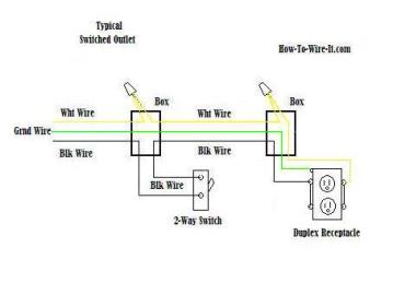
Switched Outlet Wiring Diagrams Mr Electrician
The black wire line and white neutral connect to the receptacle terminals and another 2 wire nm that travels to the next receptacle.
Receptacle wire diagram. It reveals the parts of the circuit as simplified forms as well as the power and signal links in between the tools. This article and detailed wiring diagram explains the steps to wiring the common household receptacleoutlet. Wire plugs series or parallel. How to wire plugs how does wiring them affect the electrical circuit duration.
If you do not follow these safety instructions personal injury death andor property damage may occur. It means be alert your safety is involved. According to nec an outlet is the points in an electrical wiring system where current can be taken and utilize by electrical appliances and equipment by plugging them in it. One drawback to direct wiring through a receptacle is that the receptacle is in the middle of the circuit and any trouble in the receptacle spells trouble for any devices downstream.
This is a standard 15 amp 120 volt wall receptacle outlet wiring diagram. How to with sam. In this updated diagram 3 wire cable runs between the receptacle and switch and the red cable wire is used to carry the hot source to the switch. This wiring diagram depicts the electrical power from the circuit breaker panel entering the switched electrical receptacle outlet box where a two wire cable goes to the switch and another two wire cable feeds power to another outlet that is live at all times.
Wiring a receptacle also referred to as an outlet is another of those fundamental wiring skills that every diyer should feel comfortable undertaking. Electrical outlet nec is also known as receptacle and more commonly a socket outlet iec. Starving electrician 22685 views. The neutral from the source is spliced through to the switch box using the white wire and in this diagram the white wire is capped with a wire nut.
Wiring a grounded duplex receptacle outlet. Any problem with the receptacle or even a loose wire under one of the screw terminals could cause you to lose power to the downstream circuit receptacles as well. This repeats until the end of the chain. The 15a 125v receptacle is the most widely used device in your home.
In the diagram below a 2 wire nm cable supplies line voltage from the electrical panel to the first receptacle outlet box. A grounded contact at the bottom center is crescent shaped. Connector and receptacle wirecable assembly instructions throughout this manual look for this symbol. What is an electrical outlet receptacle or socket outlet.
This is a polarized device. A wiring diagram is a streamlined traditional photographic depiction of an electric circuit.

Wrg 4083 Wiring A 220 Plug Diagram
Wiring Diagram For A Stove Plug Askmediy

Wiring Diagram Circuit Diagram Schematic Clothes Dryer Electrical

What Do Electrical Wire Color Codes Mean Angie S List

Plug Lessons Tes Teach

Wiring A Switched Outlet Wiring Diagram Power To Receptacle

Iphone Charge Plug Wire Diagram Wiring Library

220 Plug Wiring Diagrams Wiring Diagram

File Receptacle Tester Wiring Diagram Jpg Wikimedia Commons
