Relay Module Schematic Diagram

Esp8266 4 Channel Relay Module Home Automation Project Arduino

Blynking An Iot Yunshan Esp8266 250v 10a Ac Dc Wifi Network Relay

Vr 8232 Pcb Relay Board Together With 8 Pin Dpdt Relay Wiring
Typical connection to an arduino.
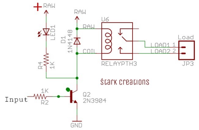
Relay module schematic diagram. It works with the 8. For demonstrating the working of this relay module we have used an arduino uno board for controlling relays. The drawing below shows the typical connections to an arduino. 12 volt relay wiring schematic.
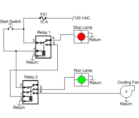
The real benefit behind a relay is more than automation. We would like to show you a description here but the site wont allow us. Variety of 12 volt solenoid wiring diagram. Fundamentally this is four separate circuits on one board.
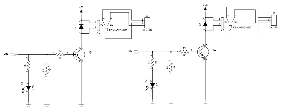
In electromechanical relays the coil accomplishes this function. Vcc and ry vcc are also the power supply of the relay module. The purpose of a relay is to automate this power to switch electrical circuits on and off at particular times. 5v arduino four channel relay schematic.
See the schematic below. Solid state relays however normally have only one output contact. Now i assume the jumpers allows the relay module to take power from the vcc of the main pin block. Car qook automotive dc 12v 12 volt 30a amp spdt wiring power relay.
A relays output circuit is the portion of the relay that switches on the load and performs the same function as the mechanical contacts of electromechanical relays. Quad channel relay board is a simple and convenient way to interface 4 relays for switching application in your project. With the vcc and jd vcc jumpered. When you need to drive a large power load you can take the jumper cap off and connect an extra power to ry vcc to supply the relay.
All of these features make sainsmart relay a great component for automation projects. Other than sharing vcc and ground the channels are isolated from one another. How to wire a raspberry pi to a sainsmart 5v relay module related product strongly recommended sainsmart 8 channels wifi remote control model. 555 integrator with transformer relay with relay schematic circuit diagram audio spectrum analyzer dspic30f6012 mcp6022 hand held simple magnetized demagnetized device schematic circuit diagram.
3 terminals per spdt relay. Input supply 12 vdc at 170 ma.
Arduino Basics

Relay Switch Circuit And Relay Switching Circuit
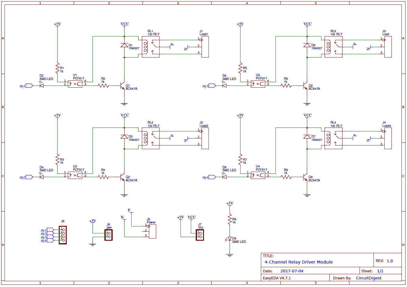
4 Channel Relay Driver Circuit And Pcb Design

Gravity Digital 5a Relay Module Module Continental Electronics

The 16 Relay Module And The Raspberry Pi Not An Ideal Marriage

8 Channel 5v Relay Module Aptofun Wiki
Generator Relays Function Of Digitally Controlled

One Channel Sugar Cube Smd Relay Board 3 Circuit Ideas I

Latching Relay Module 9 Steps With Pictures Instructables
