Resistor Wiring Diagram
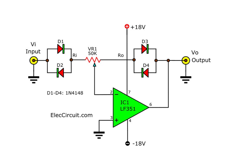
Signal Amplifier Circuit Diagram With Set Input Output Ratio
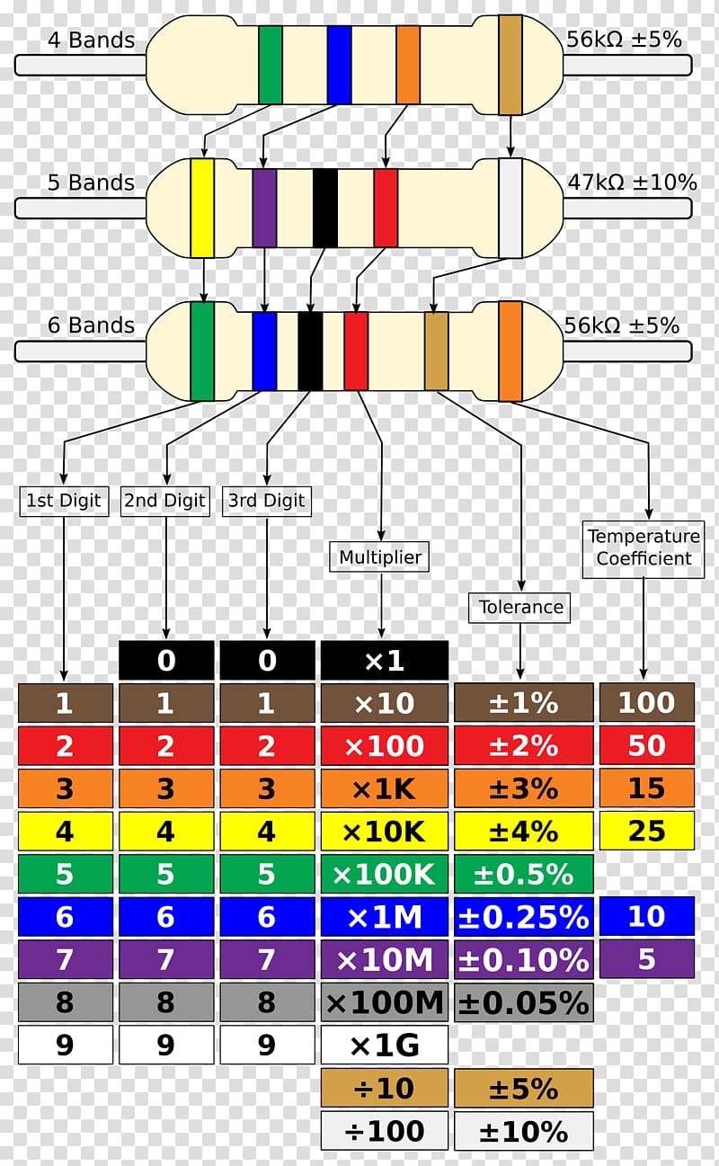
Electronic Color Code Resistor Wiring Diagram Electronic Component
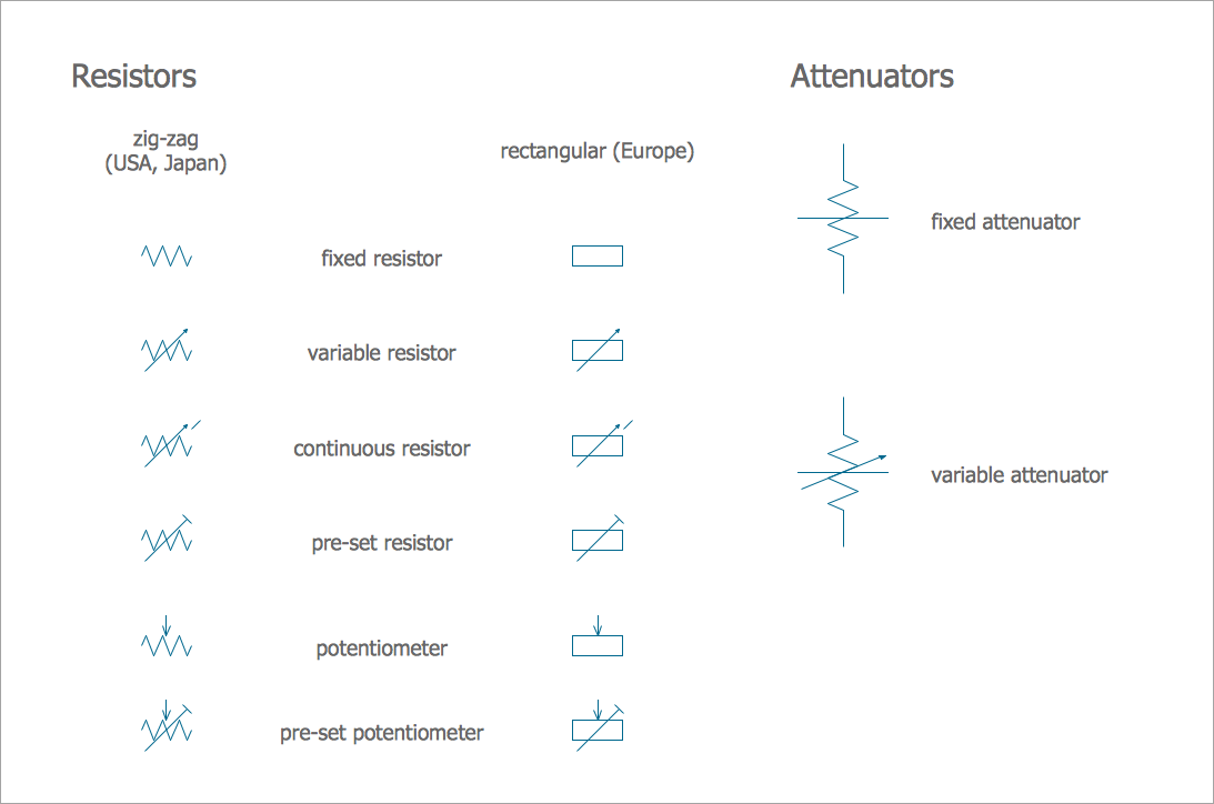
Electrical Symbols Electrical Diagram Symbols
2006 chevy silverado blower motor resistor wiring diagram.

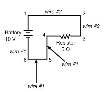
Resistor wiring diagram. Nov 09 wiring diagram for a 9n 12 volt discussion in the ford 9n 2n 8n forum at yesterdays tractors. Blower motor resistor harness 7 wire pigtail plug connector for chevy. Of course this meant that there was. Posted by anonymous on dec 11 2013.
For example 8k2 as part marking code in a circuit diagram or in a bill of materials bom indicates a. It sounds like the blower motor wire dose the motor spin this is key if the resistor wire were all bad the blower motor would still spin. Depress the latch on the blower motor resistor wire harness connector and disconnect the. Behind every component there is a resistance value and for voltage to be present there also has to be a resistance.
The notation to state a resistors value in a circuit diagram varies. Wiring diagram for resistor for blower motor 2001 jeep wrangler. The electronic resistor is the basis for any automotive wiring system. 2006 chevy silverado blower motor resistor wiring diagram wiring diagram is a simplified conventional pictorial representation of an electrical circuitit shows the components of the circuit as simplified shapes and the capability and signal links between the devices.
Ezgo golf cart wiring diagram wiring diagram for ez go 36volt systems with resistor coils club car light wiring diagram on 36v electric golf cart wiring diagram. Including switches cutouts voltage regulators ammeters battery hold down battery cables spark plug wires spark plugs resistor block and wiring harness. Golf cart wiring diagrams for club yamaha and ez go golf carts. Gas club car diagrams golf cart repair golf carts photo hosting.
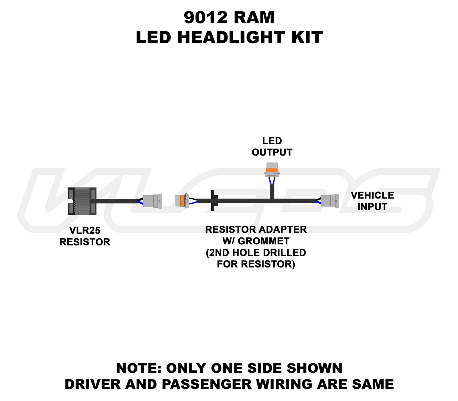
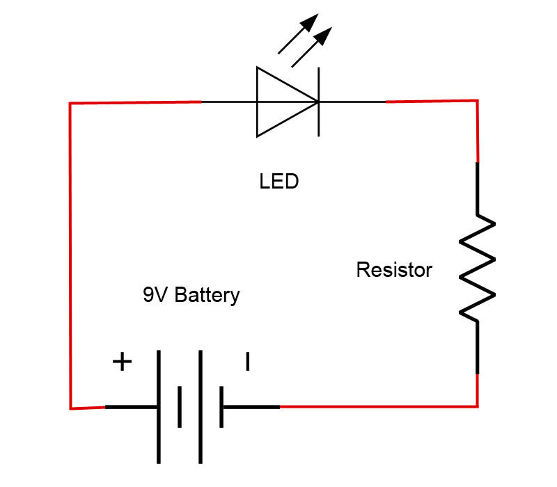
The above image shows a simple circuit to dim an led. The middle pin and one of the side pins. I recommend you get a set for your truck. If you need a simple resistor that you can change the resistance of you only need two pins.
Wiring the resistor in parallel which is the only way your calculation makes sense is a huge waste of power and actually increases the load on your electrical system over stock incandescent bulbs which is really dumb and lazy. Wiring diagram ballast resistor ignition coil. If you have connected it this way and also connected the coil to battery the coil will be constantly drawing current and will overheat and also flatten the battery. The extra resistor is there to make sure you dont destroy the led even if you change the potentiometer resistance to.
One common scheme is the rkm code following iec 60062it avoids using a decimal separator and replaces the decimal separator with a letter loosely associated with si prefixes corresponding with the parts resistance.

Kc 7131 Wiring Diagram One Wire Alternator Schematic Wiring
Circuit Diagram Electronic Circuit Electrical Network Wiring

Common Automotive Diagram Symbolsresistors Wiring Diagram
Wiring Diagrams

Tutorial 1 Building A Circuit On Breadboard For Beginners In

Light Sensor Including Photocell And Ldr Sensor
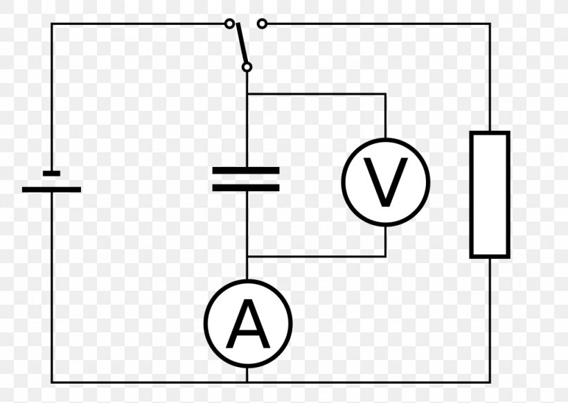
Circuit Wiring Ohm S Law Electronics Textbook
Introduction To Basic Electronics Electronic Components And Projects

Led Resistor Diagram Wiring Diagram
